Zynq-7000 AP SoC and 7 Series FPGAs MIS v4.1 122
UG586 November 30, 2016
www.xilinx.com
Chapter 1: DDR3 and DDR2 SDRAM Memory Interface Solution
Memory Controller
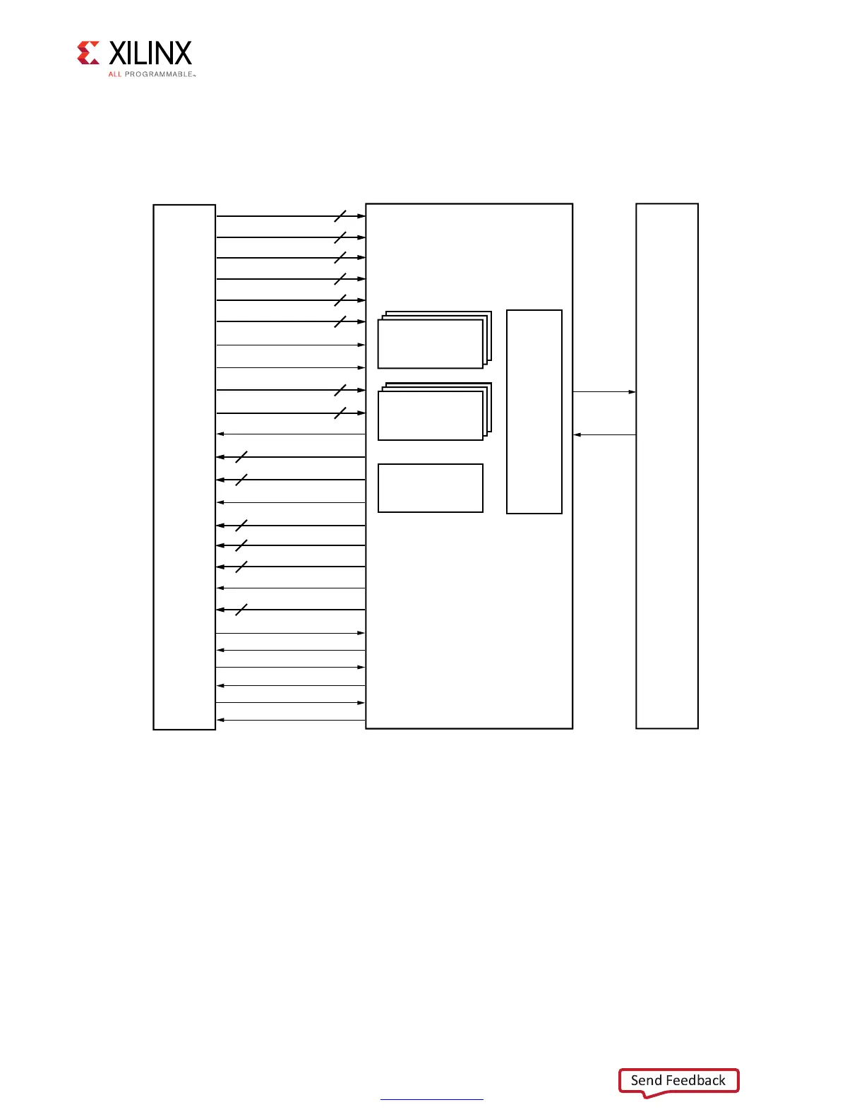
In the core default configuration, the Memory Controller (MC) resides between the UI block
and the physical layer. This is depicted in Figure 1-53.
The Memory Controller is the primary logic block of the memory interface. The Memory
Controller receives requests from the UI and stores them in a logical queue. Requests are
optionally reordered to optimize system throughput and latency.
The Memory Controller block is organized as four main pieces:
• A configurable number of “bank machines”
• A configurable number of “rank machines”
• A column machine
• An arbitration block
X-Ref Target - Figure 1-53
Figure 1-53: Memory Controller
RANK
BANK
ROW
COL
CMD
DATA?BUF?ADDR
HI?PRIORITY
USE?ADDR
WR?DATA
WR?DATA?MASK
ACCEPT
BANK?MACH?NEXT
WR?DATA?ADDR
WR?DATA?EN
WR?DATA?OFFSET
RD?DATA
RD?DATA?ADDR
RD?DATA?EN
RD?DATA?OFFSET
2ANK-ACHINES
"ANK-ACHINES
!RBITER
-#0(9
)NTERFACE
0HYSICAL
,AYER
5SER
)NTERFACE
"LOCK
#OLUMN-ACHINE
5'?C??
APP?SR?REQ
APP?SR?ACTIVE
APP?REF?REQ
APP?REF?ACK
APP?ZQ?REQ
APP?ZQ?ACK
 Loading...


