Zynq-7000 AP SoC and 7 Series FPGAs MIS v4.1 505
UG586 November 30, 2016
www.xilinx.com
Chapter 3: RLDRAM II and RLDRAM 3 Memory Interface Solutions
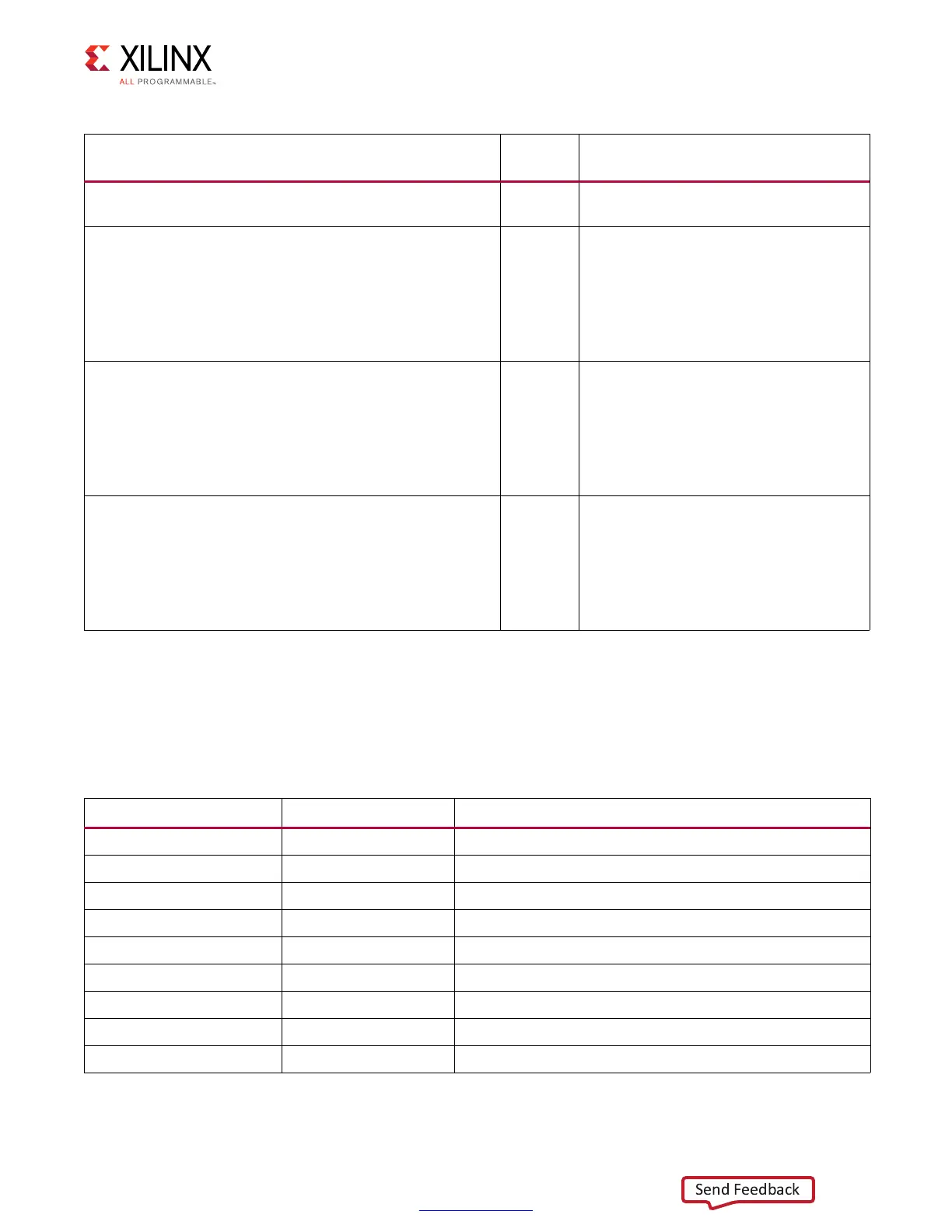
Write Init Debug Signals
Table 3-29 indicates the mapping between the write init debug signals on the
dbg_wr_init bus and debug signals in the PHY. All signals are found within the
rld_phy_write_init_sm module and are all valid in the clk domain.
dbg_wrcal_done[2:0] Output
Indicates stage of write calibration
completed.
dbg_wrcal_po_first_edge[5:0] Output
First edge of write calibration window
found for the selected byte lane (using
dbg_byte_sel). To select a given stage of
calibration, use dbg_wrcal_sel_stg, 2'b01
is for byte lanes with a DK clock, and
2'b10 is for byte lanes without a DK
clock.
dbg_wrcal_po_second_edge[5:0] Output
Second edge of write calibration window
found for the selected byte lane (using
dbg_byte_sel). To select a given stage of
calibration, use dbg_wrcal_sel_stg, 2'b01
is for byte lanes with a DK clock, and
2'b10 is for byte lanes without a DK
clock.
dbg_wrcal_po_final[5:0] Output
Final tap setting for write calibration for
the selected byte lane (using
dbg_byte_sel). To select a given stage of
calibration, use dbg_wrcal_sel_stg, 2'b01
is for byte lanes with a DK clock, and
2'b10 is for byte lanes without a DK
clock.
Table 3-28: DEBUG_PORT Signal Descriptions (Cont’d)
Signal Direction Description
Table 3-29: Write Init Debug Signal Map
Bits PHY Signal Name Description
dbg_phy_init_sm[3:0] phy_init_cs Current state of the initialization state machine
dbg_phy_init_sm[6:4] start_cal Flags to determine stages of calibration
dbg_phy_init_sm[7] init_complete Memory initialization is complete
dbg_phy_init_sm[8] refr_req Refresh request
dbg_phy_init_sm[9] refr_done Refresh complete
dbg_phy_init_sm[10] stage2_done Stage 2 calibration is complete
dbg_phy_init_sm[22:11] refr_cnt Refresh counter
dbg_phy_init_sm[26:23] phy_init_ps Previous state of the initialization state machine
dbg_phy_init_sm[31:27] Reserved Reserved
 Loading...


