Zynq-7000 AP SoC and 7 Series FPGAs MIS v4.1 29
UG586 November 30, 2016
www.xilinx.com
Chapter 1: DDR3 and DDR2 SDRAM Memory Interface Solution
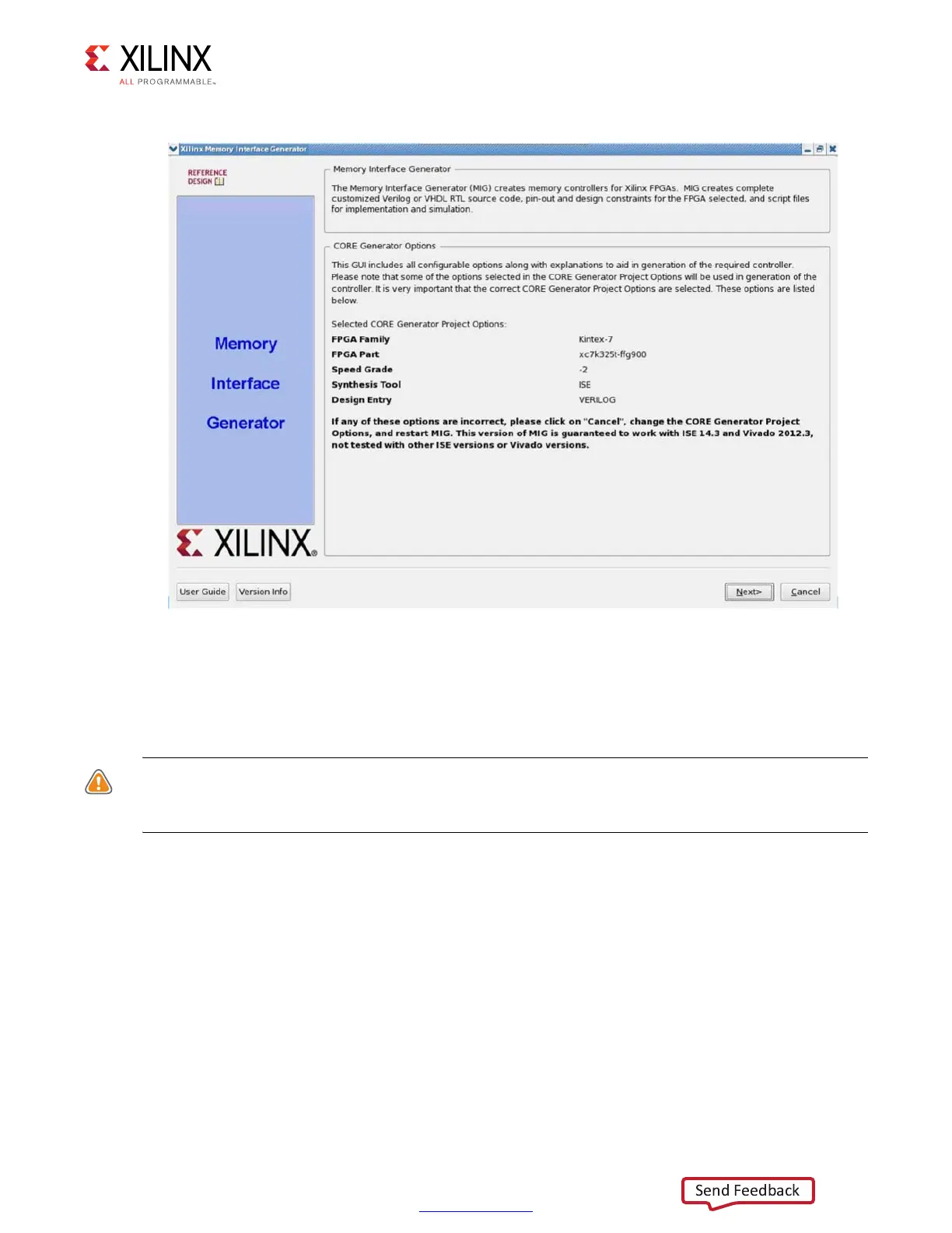
13. Select MIG 7 Series to open the MIG tool (Figure 1-13).
14. Click Next to display the Output Options page.
Customizing and Generating the Core
CAUTION! The Windows operating system has a 260-character limit for path lengths, which can affect
the Vivado tools. To avoid this issue, use the shortest possible names and directory locations when
creating projects, defining IP or managed IP projects, and creating block designs.
MIG Output Options
1. Select the Create Design to create a new Memory Controller design. Enter a component
name in the Component Name field (Figure 1-14).
2. Choose the number of controllers to be generated. This option determines the
replication of further pages.
3. DDR2 and DDR3 SDRAM designs support the memory-mapped AXI4 interface. The AXI4
interface is implemented in Verilog only. If an AXI4 interface is required, select the
language as “Verilog” in the Vivado Design Suite before invoking the MIG tool. If the
AXI4 interface is not selected, the user interface (UI) is the primary interface.
X-Ref Target - Figure 1-13
Figure 1-13: 7 Series FPGAs Memory Interface Generator FPGA Front Page
 Loading...


