Zynq-7000 AP SoC and 7 Series FPGAs MIS v4.1 92
UG586 November 30, 2016
www.xilinx.com
Chapter 1: DDR3 and DDR2 SDRAM Memory Interface Solution
When a user creates a multicontroller design on their own, each MIG output has the
component instantiated with the primitive. This violates the rules for IDELAYCTRLs and the
usage of the IODELAY_GRP attribute. IDELAYCTRLs need to have only one instantiation of
the component with the attribute set properly, and allow the tools to replicate as needed.
User Interface
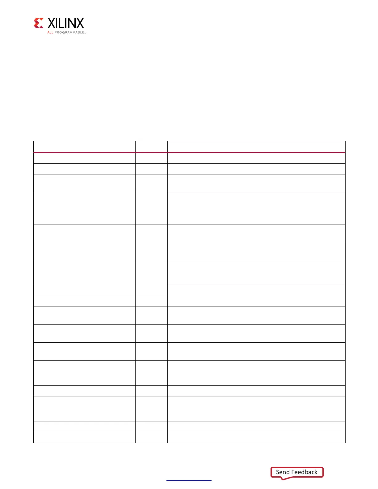
The UI is shown in Table 1-17 and connects to an FPGA user design to allow access to an
external memory device.
Table 1-17: User Interface
Signal Direction Description
app_addr[ADDR_WIDTH – 1:0] Input This input indicates the address for the current request.
app_cmd[2:0] Input This input selects the command for the current request.
app_en Input
This is the active-High strobe for the app_addr[], app_cmd[2:0],
app_sz, and app_hi_pri inputs.
app_rdy Output
This output indicates that the UI is ready to accept commands.
If the signal is deasserted when app_en is enabled, the current
app_cmd and app_addr must be retried until app_rdy is
asserted.
app_hi_pri Input
This active-High input elevates the priority of the current
request.
app_rd_data
[APP_DATA_WIDTH – 1:0]
Output This provides the output data from read commands.
app_rd_data_end Output
This active-High output indicates that the current clock cycle is
the last cycle of output data on app_rd_data[]. This is valid only
when app_rd_data_valid is active-High.
app_rd_data_valid Output This active-High output indicates that app_rd_data[] is valid.
app_sz Input This input is reserved and should be tied to 0.
app_wdf_data
[APP_DATA_WIDTH – 1:0]
Input This provides the data for write commands.
app_wdf_end Input
This active-High input indicates that the current clock cycle is
the last cycle of input data on app_wdf_data[].
app_wdf_mask
[APP_MASK_WIDTH – 1:0]
Input This provides the mask for app_wdf_data[].
app_wdf_rdy Output
This output indicates that the write data FIFO is ready to receive
data. Write data is accepted when app_wdf_rdy = 1’b1 and
app_wdf_wren = 1’b1.
app_wdf_wren Input This is the active-High strobe for app_wdf_data[].
app_correct_en_i Input
When asserted, this active-High signal corrects single bit data
errors. This input is valid only when ECC is enabled in the GUI.
In the example design, this signal is always tied to 1.
app_sr_req Input This input is reserved and should be tied to 0.
app_sr_active Output This output is reserved.
 Loading...


