Zynq-7000 AP SoC and 7 Series FPGAs MIS v4.1 321
UG586 November 30, 2016
www.xilinx.com
Chapter 2: QDR II+ Memory Interface Solution
Interfacing with the Core through the Client Interface
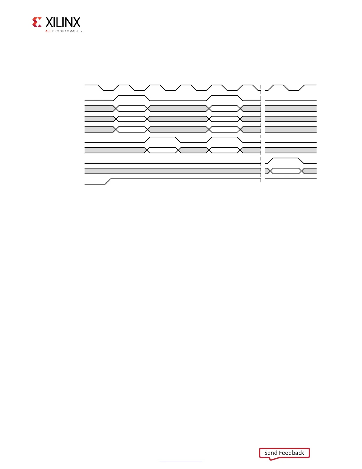
The client interface protocol is the same for using the port 0 or port 1 interface signals and
is shown in Figure 2-40.
Before any requests can be made, the init_calib_complete signal must be asserted
High, as shown in Figure 2-40, no read or write requests can take place, and the assertion of
app_wr_cmd or app_rd_cmd on the client interface is ignored. A write request is issued by
asserting app_wr_cmd as a single cycle pulse. At this time, the app_wr_addr,
app_wr_data, and app_wr_bw_n signals must be valid.
On the following cycle, a read request is issued by asserting app_rd_cmd for a single cycle
pulse. At this time, app_rd_addr must be valid. After one cycle of idle time, a read and
write request are both asserted on the same clock cycle. In this case, the read to the
memory occurs first, followed by the write.
Figure 2-40 also shows data returning from the memory device to the user design. The
app_rd_vld signal is asserted, indicating that app_rd_data is now valid. This should be
sampled on the same cycle that app_rd_vld is asserted because the core does not buffer
returning data. If desired, you can add this functionality. The data returned is not necessarily
from the read commands shown in Figure 2-40 and is solely to demonstrate protocol.
X-Ref Target - Figure 2-40
Figure 2-40: Components of the QDR II+ SRAM Memory Interface Solution
5'?C??
APP?WR?CMD
APP?WR?ADDR
APP?WR?DATA
APP?WR?BW?N
APP?RD?CMD
APP?RD?ADDR
APP?RD?DATA
INIT?CALIB?COMPLETE
APP?RD?VLD
CLK
72?!$$2 72?!$$2
72?$!4! 72?$!4!
72?"7?. 72?"7?.
2$?!$$2 2$?!$$2
2$?$!4!
 Loading...


