Zynq-7000 AP SoC and 7 Series FPGAs MIS v4.1 159
UG586 November 30, 2016
www.xilinx.com
Chapter 1: DDR3 and DDR2 SDRAM Memory Interface Solution
The second module, ddr_phy_tempmon, resides in the top-level calibration module,
calib_top. It receives the device_temp[11:0] from the tempmon module and an
enable signal from the Memory Controller. The enable signal is set by the Memory
Controller whenever a REF or ZQ command has been sent to the DRAM and all pending
transactions have cleared the DQ bus. The temperature value is sampled on the clock when
the enable transitions from Low to High.
User designs utilizing the PHY-only design must drive the tempmon_sample_en input
every time a ZQ or REF is sent. It should be brought High after all pending reads have been
received through the ISERDES and held until the REF or ZQ has completed and an ACT is
ready to be sent. After calibration has completed and the enable signal is set, the
ddr_phy_tempmon samples the device_temp[11:0] bus and establishes a baseline
temperature.
After each subsequent enable, the current temperature is compared to the baseline
temperature. If the temperature change is sufficient, the module adjusts the PHASER_IN
fine delay to mitigate temperature drift. This process continues throughout normal
operation.
Memory Controller to PHY Interface
The calibration logic module constructs the PHY control word before sending it to the PHY
control block during calibration. After calibration is complete, the
init_calib_complete signal is asserted and sent to the Memory Controller to indicate
that normal operation can begin. To avoid latency increase, the Memory Controller must
send commands in the format required by the dedicated PHY block. As a result, the address,
command, control, and data buses are multiplexed before being sent to the PHY control
block. These buses are driven by the calibration module during the memory initialization
and calibration stages and by the Memory Controller during normal operation. Table 1-61
describes the Memory Controller to PHY interface signals. These signals are synchronous to
the FPGA logic clock.
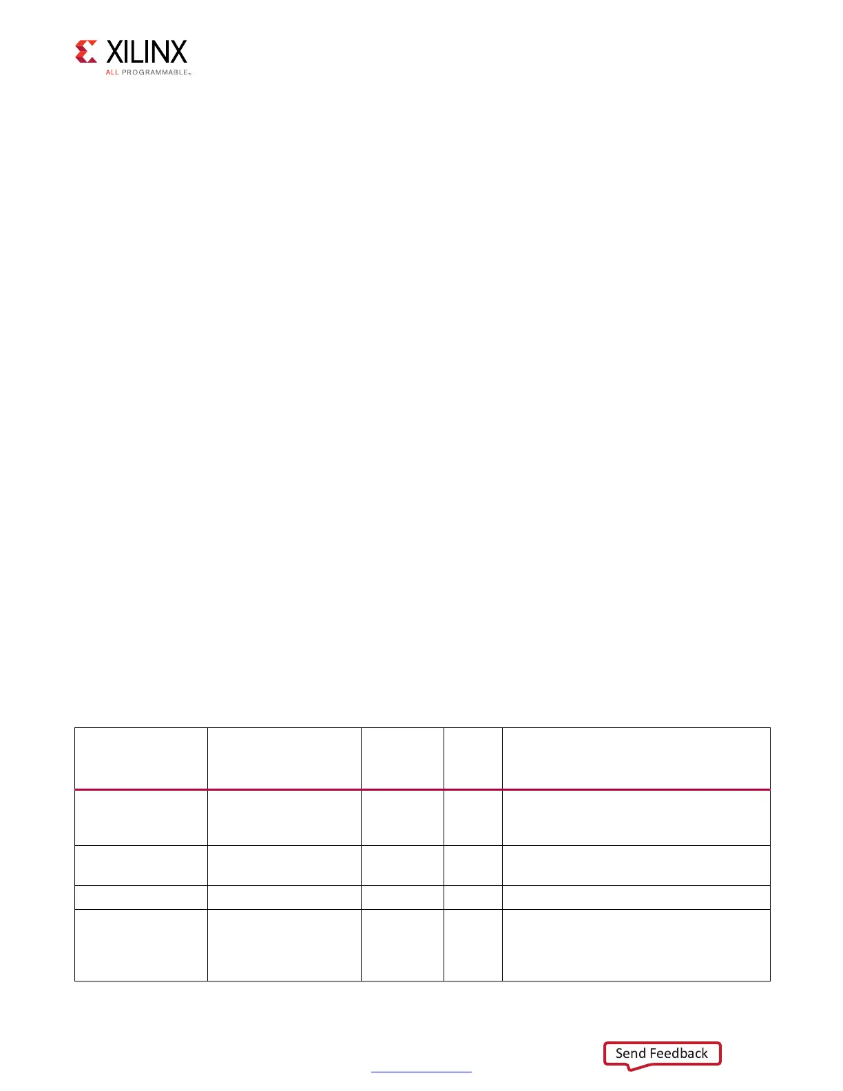
Table 1-61: Memory Controller to Calibration Logic Interface Signals
Signal Name Width
I/O
To/From
PHY
Type Description
rst 1 Input –
The rstdiv0 output from the infrastructure
module synchronized to the PHY_Clk
domain.
PHY_Clk 1 Input –
This clock signal is 1/4 the frequency of
the DDR2 or DDR3 clock.
mem_refclk 1 Input – This is the DDR2 or DDR3 frequency clock.
freq_refclk 1 Input –
This signal is the same frequency as
mem_refclk between 400 MHz to
933 MHz, and 1/2 or 1/4 of mem_refclk for
frequencies below 400 MHz.
 Loading...


