9980 Self-Propelled Peanut Combine Electrical System Service
Radio Installation
Electronic equipment, such as a
communication or CB radio, can be connected
to the auxiliary power outlet located behind the
operator’s seat. The auxiliary power outlet
contains two 30 AMP terminals for quick
accessible power. Order (1) RE57072
connector from service parts to connect the
auxiliary power outlet to your electronic
equipment.
FM Radio
Use the
chart below to determine the circuit
breaker and wire size needed for your radio.
These are only guidelines; consult your radio
manual for actual values.
FM RADIO OUTPUT POWER TO CIRCUIT
BREAKER/WIRE GAUGE
Radio
Output
Power
Approx.
Circuit
Protection
Circuit
Breaker
Size and
Wire
Size
Aver.
10 5 AMPS 6A-AT41395 16
20 10 AMPS
10A-
AT42014
AR55649
14
30 15 AMPS
12
40 20 AMPS
20A-
AT41394
10
50 25 AMPS
25A-
AM33621
10
60** 30 AMPS
30A-
AR49352
8
80** 40 AMPS
40A-
AT29162
8
100** 50 AMPS
50A-
AH112189
8
**If two input power leads are needed for your
radio, the wire size shown is for the transmit
section only. Consult your radio manual for
the low current requirements.
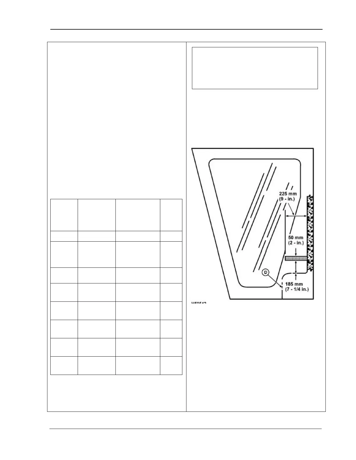
Use the following guidelines for radio
installation:
• The circuit breakers should be mounted to
the sides of the relay panel (see sketch
below).
•
Due to the different styles available, the
circuit breaker’s mounting feet should be
used as a template for drilling the mounting
holes.
• Route the power wire from the circuit
breakers through the cab wall connector
plate grommet to the radio along the left
main wiring harness.
•
Use a protective harness covering
anywhere that the wire insulation might
come into contact with sharp edges.
NOTE! For a radio with under 5 watts
output power, you can use the power
leads supplied with the machine. If this
is not desirable, use the wire and circuit
breaker for a 10 watt radio.
MAN141 09/04/15 267