Reference Manual ADuCM356
REGISTER DETAILS: ADC CIRCUIT
analog.com Rev. A | 70 of 312
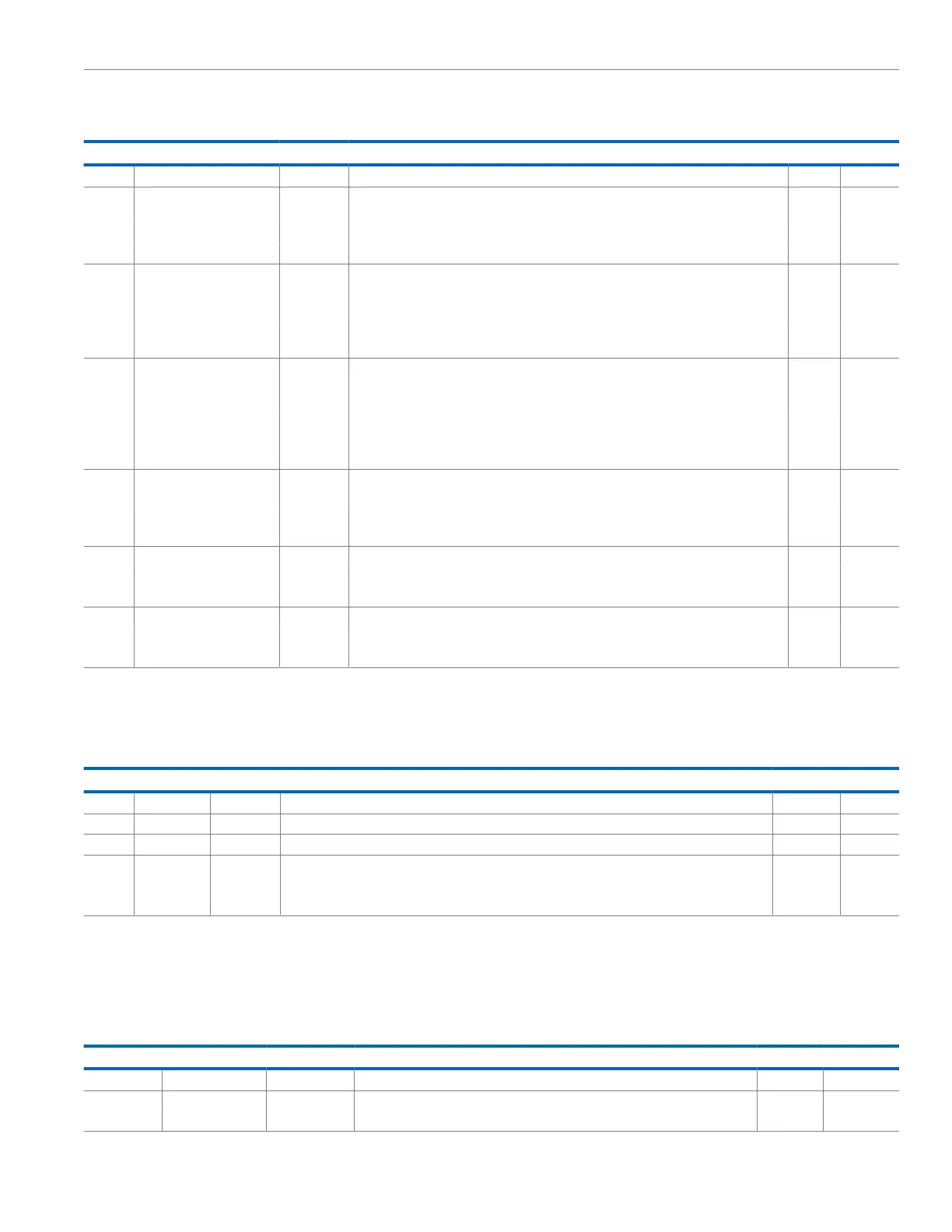
Table 74. Bit Descriptions for BUFSENCON (Continued)
Bits Bit Name Settings Description Reset Access
1 Close Switch. Close this switch to connect the 1.1 V reference to the discharging circuit.
5 V1P1LPADCEN ADC 1.1 V Low-Power Common-Mode Buffer. Optional. Use either high-power or low-power
reference buffer.
0x1 R/W
0 Disable ADC 1.1 V low-power reference buffer.
1 Enable ADC 1.1 V low-power reference buffer.
4 V1P1HPADCEN Enable 1.1 V High-Power Common-Mode Buffer. Controls buffer for 1.1 V. Common-mode
voltage source to ADC input stage.
0x1 R/W
0 Disable 1.1 V high-power common-mode buffer.
1 Enable 1.1 V high-power common-mode buffer. Recommended value for normal ADC
operation.
3 V1P8HPADCCHGDIS Controls Decoupling Capacitor Discharge Switch. This switch connects the 1.8 V internal
ADC reference to an internal discharging circuit. Ensure that the switch is open for normal
operation to maintain the reference voltage on the external decoupling capacitor.
0x0 R/W
0 Open switch. If opened, the voltage on the external decoupling capacitor for the reference is
maintained. Recommended setting.
1 Close Switch. Close this switch to connect the reference to the discharge circuit.
2 V1P8LPADCEN ADC 1.8 V Low-Power Reference Buffer. 0x1 R/W
0 Disable low-power 1.8 V reference buffer.
1 Enable low-power 1.8 V reference buffer. Recommended value. Speeds up settling time
when exiting power-down states.
1 V1P8HPADCILIMITEN High-Power ADC Input Current Limit. Protects ADC input buffer. 0x1 R/W
0 Disable buffer current limit.
1 Enable buffer current limit. Recommended setting.
0 V1P8HPADCEN High-Power 1.8 V Reference Buffer. Enable for normal ADC conversions. 0x1 R/W
0 Disable 1.8 V high-power ADC reference buffer.
1 Enable 1.8 V high-power ADC reference buffer.
NUMBER OF REPEAT ADC CONVERSIONS REGISTER
Address: 0x400C21F0, Reset: 0x00000160, Name: REPEATADCCNV
Table 75. Bit Descriptions for REPEATADCCNV
Bits Bit Name Settings Description Reset Access
[31:5] Reserved Reserved. 0x00016 R
[4] NUM Write 1 to this bit to enable single or continuous conversion. 0x0 R
[3:1] Reserved Reserved. 0x0 R
0 EN Enable Repeat ADC Conversions. 0x0 R/W
0 Disable repeat ADC conversions.
1 Enable repeat ADC conversions.
BUFFER CONFIGURATION REGISTER
Address: 0x400C238C, Reset: 0x005F3D00, Name: ADCBUFCON
The recommended value for this register is 0x005F3D0F in high-power mode and 0x005F3D04 in low-power mode.
Table 76. Bit Descriptions for ADCBUFCON
Bits Bit Name Settings Description Reset Access
[31:4] Reserved Reserved. 0x0 R
3 CHOPDIS Configure Offset Cancellation Buffer Chop. 0x0 R/W
0 Enable chop.
 Loading...