Reference Manual ADuCM356
SEQUENCER
analog.com Rev. A | 128 of 312
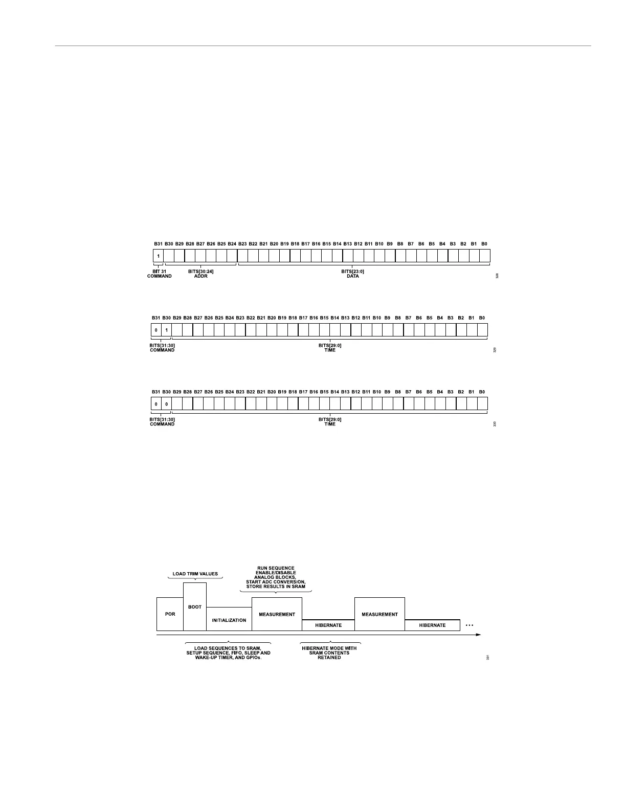
Figure 29 shows the format of the timer command, and Figure 30
shows the format of the wait command.
The timeout command starts a counter that operates independently
of the sequencer flow. When the timer elapses, one of two inter-
rupts is generated: a sequencer timeout error interrupt (INTSEL17)
or a sequencer timeout finished interrupt (INTSEL16). Both inter-
rupts are configured in the INTCSELx registers. The sequence
timeout finished interrupt is asserted at the end of the timeout
period. The sequence timeout error interrupt is asserted if the
sequencer does not reach the end of execution at the end of
the timeout period. These interrupts are cleared by writing to the
corresponding bits in the INTCCLR register. The current value of
the counter can be read by the host controller at any time through
the SEQTIMEOUT register.
The timeout counter is not reset when the sequencer execution is
stopped as a result of a sequencer write command. However, the
counter resets if the host controller writes a 0 to the SEQEN bit
in the SEQCON register. This reset applies to situations when the
host must abort the sequence.
The time unit for both timer commands is one ACLK period. For a
clock frequency of 16 MHz, the timer resolution is 62.5 ns and the
maximum timeout is 67.1 sec. These values are still true when the
SEQWRTMR bits in the SEQCON register are nonzero.
Figure 28. Sequencer Write Command
Figure 29. Sequencer Timer Command
Figure 30. Sequencer Wait Command
SEQUENCER OPERATION
Figure 31 shows the typical steps required to set up the sequencer
to take measurements. When the device is booted up, take the
following steps to configure the sequencer, command memory, and
data FIFO:
1. Configure the command memory.
2. Load the sequences into the SRAM.
3. Set the Sequence 0 (SEQ0) to Sequence 3 (SEQ3) information
sequences.
4. Configure the data FIFO.
5. Configure the sleep and wake-up timer.
6. Configure the interrupts.
7. Configure the sleep and wake-up method.
Figure 31. Run Sequence
Command Memory
The command memory stores the sequence commands and pro-
vides a link between the external microcontroller and the sequenc-
er. The command memory can be configured to use the 2 kB, 4
kB, and 6 kB SRAM memory sizes, which are selected using the
CMDDATACON register, Bits[2:0].
The large amount of memory available for the command memory
facilitates the creation of larger, more complex sequences.
 Loading...