Reference Manual ADuCM356
ADC CIRCUIT
analog.com Rev. A | 53 of 312
ADC CIRCUIT OVERVIEW
The SAR ADC circuit is implemented on the analog die. The die
operates from a 2.8 V to 3.6 V power supply. The Arm Cortex-M3
processor interfaces to the ADC via an internal die-to-die interface.
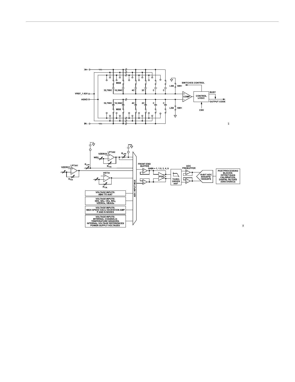
The ADC uses a precision, low drift, factory calibrated 1.82 V
reference. An external reference can also be connected to the
VREF_1.82V pin. ADC conversions can be triggered by writing
directly to the AFECON register.
Figure 7. ADC Core Block Diagram
Figure 8. ADC Input Stages
ADC CIRCUIT FEATURES
The ADuCM356 includes a fast multichannel, 16-bit ADC. The input
multiplexer supports a number of external and internal channels.
There are up to 34 user-selectable channels, including the follow-
ing:
► Four low-power current measurement channels. These channels
are designed to measure the sense, working, and diagnostic
electrode outputs of electrochemical sensors. The current chan-
nels feed into a programmable load resistor (R
LOAD
).
► Includes two low-power TIAs, each containing a programma-
ble gain resistor to convert very small currents to a voltage
signal that the ADC can measure.
► The low-power current channels can be configured to sample
with a low-pass filter in place. Bypassing the low-pass filter
can be useful for diagnostic operations on an electrochemical
sensor output.
► One high-speed current input channel for performing impedance
measurements up to 200 kHz. This channel has dedicated TIAs
with a programmable gain resistor.
► Multiple external voltage inputs.
► Eight dedicated voltage input channels, AIN0 to AIN7.
► The sensor electrode pins can also be measured as ADC
voltage inputs.
► The SE0, SE1, DE0, RE0, RE1, CE0, and CE1 pins are
included. Divide by two options are available for the CE0 and
CE1 inputs.
► Internal ADC channels.
► AVDD, DVDD, and AVDD_REG are power supply measure-
ment channels.
► ADC, high-speed DAC, and low power reference voltage
inputs.
► Two internal die temperature sensors.
► Four low-power DAC output voltages: VBIAS0, VZERO0,
VBIAS1, and VZERO1.
 Loading...