Reference Manual ADuCM356
USE CASE CONFIGURATIONS
analog.com Rev. A | 154 of 312
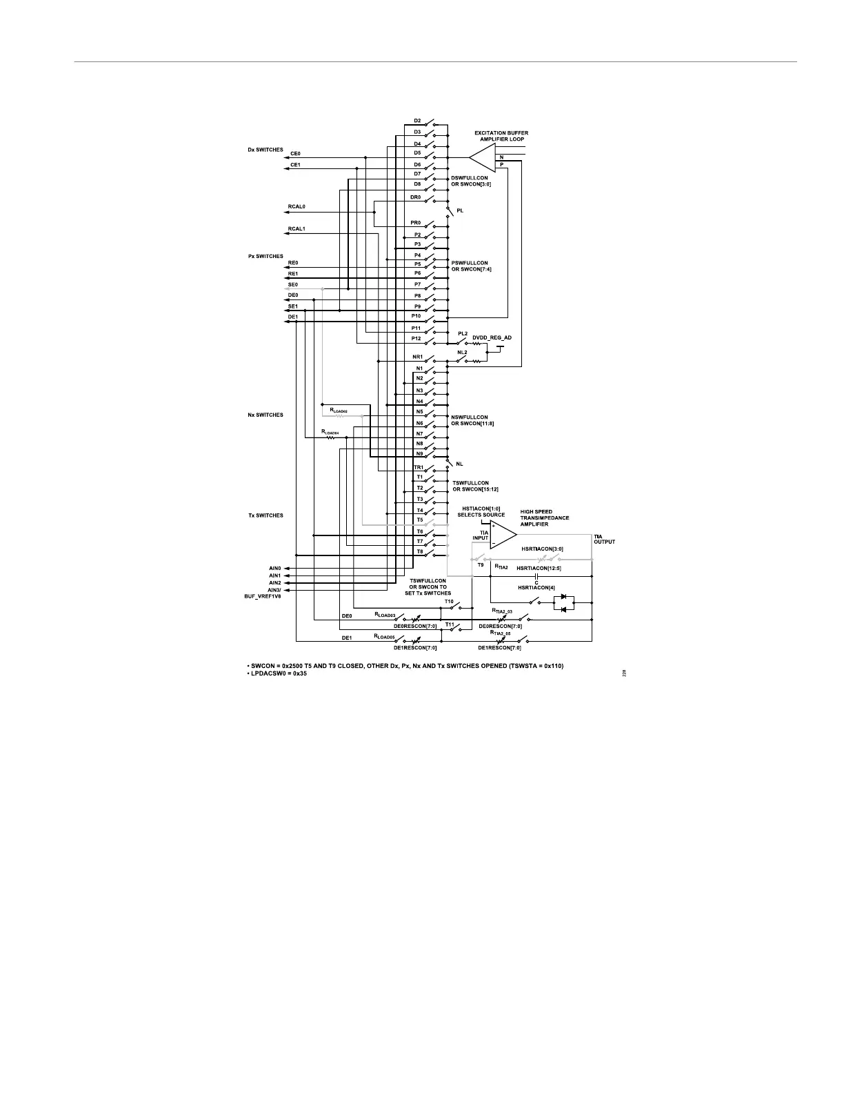
Figure 40. Signal Path for Low-Power Potentiostat, Low-Power TIA, and Switch Matrix to Perform Cyclic Voltammetry or Pulse Test on SE0 Node Using High-Speed
TIA
Exiting Cyclic Voltammetry Mode
When exiting voltammetry mode to return to biasing the sensor
normally or to resume taking DC measurements, take care to
minimize the sensor settling time, as follows:
1. Before adjusting the switches for a normal DC bias, reconfigure
the low-power DAC outputs to their required DC levels. Write to
the LPDACDAT0 register or the LPDACDAT1 register.
2. Disconnect the high-speed TIA circuitry from the sensor. Open
the T10 and T11 switches of the switch matrix by clearing
TSWFULLCON, Bits[10:9] = 0b00. Disconnect the high-speed
TIA gain resistors by setting DE0RESCON and DE1RESCON
to 0xFF. Optionally, to save power, power down the high-speed
TIA by clearing AFECON, Bit 11 = 0.
3. Configure the low-power DAC switches for normal DC meas-
urements. Write LPDACSWx = 0. Clear LPDACCONx, Bit 5 = 0
for normal switch operation around the low-power DACs. Set up
LPDACCONx, Bits[4:3] to set V
BIAS
and V
ZERO
to 12-bit or 6-bit
mode.
4. After configuring the low-power DAC, set up the low-power TIA.
Set the low-power TIA switches for normal operation. Optional-
ly, the SW0 and SW1 switches around the low-power TIA can
be closed for a short duration to allow the low-power TIA to
charge up the sensor, allowing the SE0 node of the sensor
to settle faster to the VZEROx output bias voltage setting.
See Figure 16 to locate SW0 and SW1 in the low-power TIA
circuitry.
AC IMPEDANCE MEASUREMENT WHILE
MAINTAINING DC BIAS TO THE SENSOR
The following sections detail an example configuration setup for an
AC impedance measurement of <80 kHz. The impedance measure-
 Loading...