71 - Maintenance Procedures
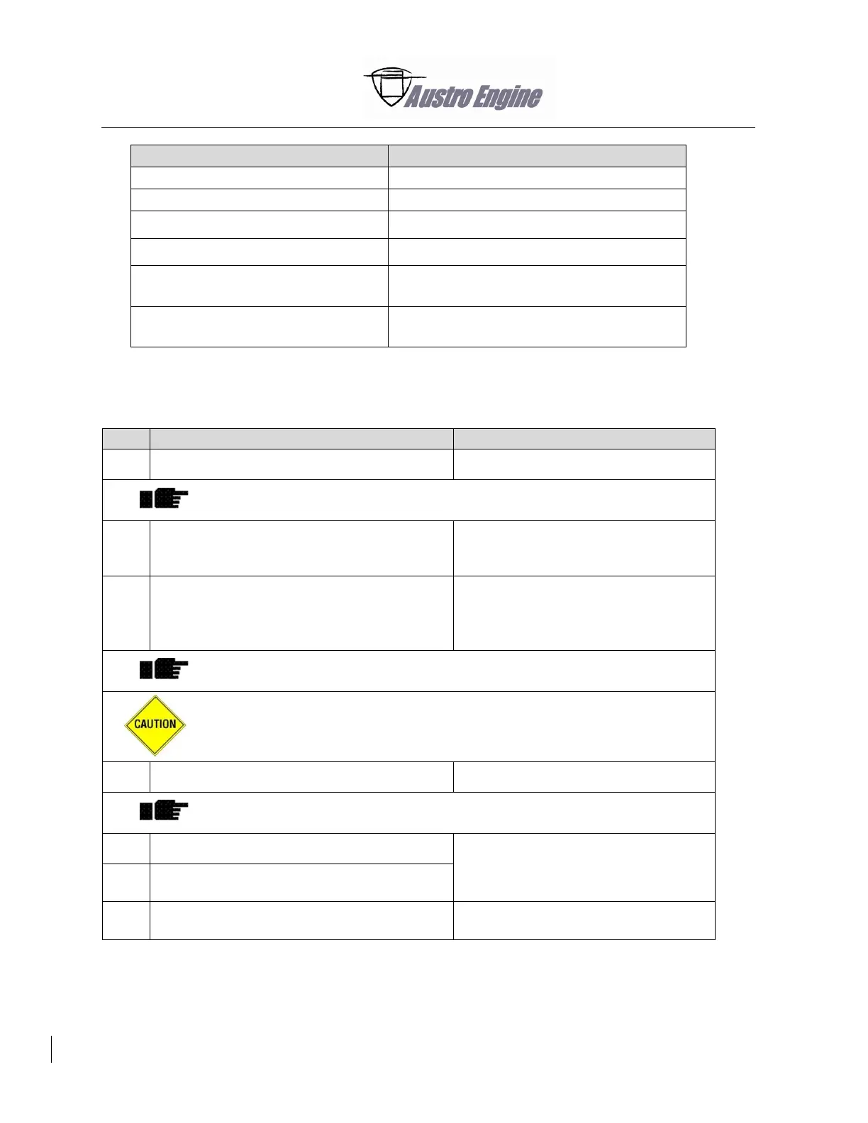
AD-1377 by TE Connectivity
Crimp tool for Inline crimp
58433-3 by TE Connectivity
Recommended Crimp tool for ring terminal
(TE Connectivity)
58423-1 by TE Connectivity
Recommended DIE Set for crimp tool (TE
Connectivity)
Table 71 - 3 Special Tools
Cut off the defective cable branch.
It is recommended to cut the cable branch behind the solder sleeve of the
pigtail.
Make sure that the repair kit cable is
sufficiently long to connect the remaining
harness to the repair kit.
If a ring terminal at the end of the pigtail is
shared between multiple branches:
- Cut off the ring terminal as near to the ring
terminal as possible.
Shared ring terminals are only on IAT1 & BPS1, and IAT2 and BPS2.
Do not cut into the shielding braid!
Cut and remove 50 mm of the white isolation.
For CTS_GPC, INJ1, INJ2, INJ3, INJ4 repair, cut off all the shielding braid
and continue with Step (10).
Cut off 40 mm of the shielding braid.
Fold the remaining shielding braid back over
the white isolation.
Put the solder sleeve directly over the
shielding braid.
Use a hot air gun (300°C – 350°C).