▶
Insert all dummy modules, see "Installing a 2.5-inch HDD/SSD dummy
module" on page 170
.
▶
"Connecting the power cord" on page 65.
▶
"Switching on the server" on page 69.
▶
If applicable, "Installing the front cover with lock" on page 69.
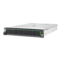
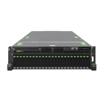
7.5.9 Replacing a 24x 2.5-inch HDD backplane and a
switch board
The 24x 2.5-inch HDD backplane and the switch board are combined
into one spare part.
Field Replaceable Unit
(FRU)
Hardware: 15 minutes
Tools: Phillips PH2 / (+) No. 2 screw driver
Preliminary steps
▶
"Locating the defective server" on page 49
.
▶
If applicable, "Removing the front cover with lock" on page 52.
▶
"Shutting down the server" on page 52.
▶
"Disconnecting the power cord" on page 53.
▶
"Getting access to the component" on page 56.
▶
Release all PCIe SSD modules and pull them out a few centimeters, see
"Removing a 2.5-inch HDD/SSD module" on page 169.
The PCIe SSD modules need not to be removed. But if you want to
remove them nevertheless, check if all PCIe SSD modules are
uniquely identified so that you can reinsert them into their original
bays.
▶
Release all dummy modules and pull them out a few centimeters, see
"Removing a 2.5-inch HDD/SSD dummy module" on page
165.
Hard disk drive (HDD) / solid state disk (SSD)
184 Upgrade and Maintenance Manual RX2540 M6
 Loading...
