RX300 S8
Upgrade and Maintenance Manual 491
Appendix
17.3.2 Connectors and indicators on the I/O panel
17.3.2.1 I/O panel connectors
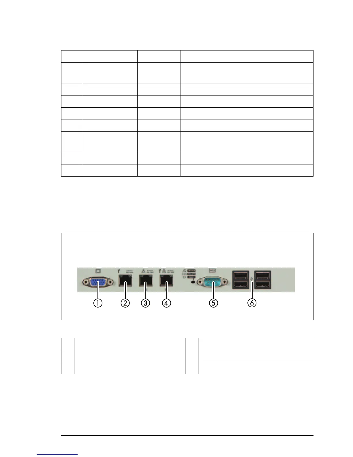
Figure 342: PRIMERGY RX300 S8 rear
Depending on BIOS settings, the shared LAN connector may also be used as
a management LAN connector. For further information, please refer to the
corresponding BIOS Setup Utility reference manual.
H
Memory
module
orange on memory module faulty
I PS CTRL OK green on power supply OK
K PS CTRL Error orange on power supply error
L Main power green on voltage ok
M Standby power yellow on voltage ok
N iRMC
green
flashing
iRMC S4 ok
O Fans orange on system fan faulty
P Battery orange on battery faulty
1 Video connector (blue) 4 Shared LAN connector (LAN 1)
2 Management LAN connector 5 Serial connector COM1(turquoise)
3 Standard LAN connector (LAN 2) 6 4 USB connectors (black)
Indicator Status Description

 Loading...