1126800 SmartPAC 2 with WPC Integration
Page 88 Chapter 2 Installing SmartPAC 2 and WPC
Table 2 - 7. Making Connections to Relays
Module How to connect Type
Relay one wire to C; one wire to N/O or N/C; polarity does not matter SPDT
DC Solid State – to C; + to N/O SPST
AC Solid State one wire to C; one wire to N/O; polarity does not matter SPST
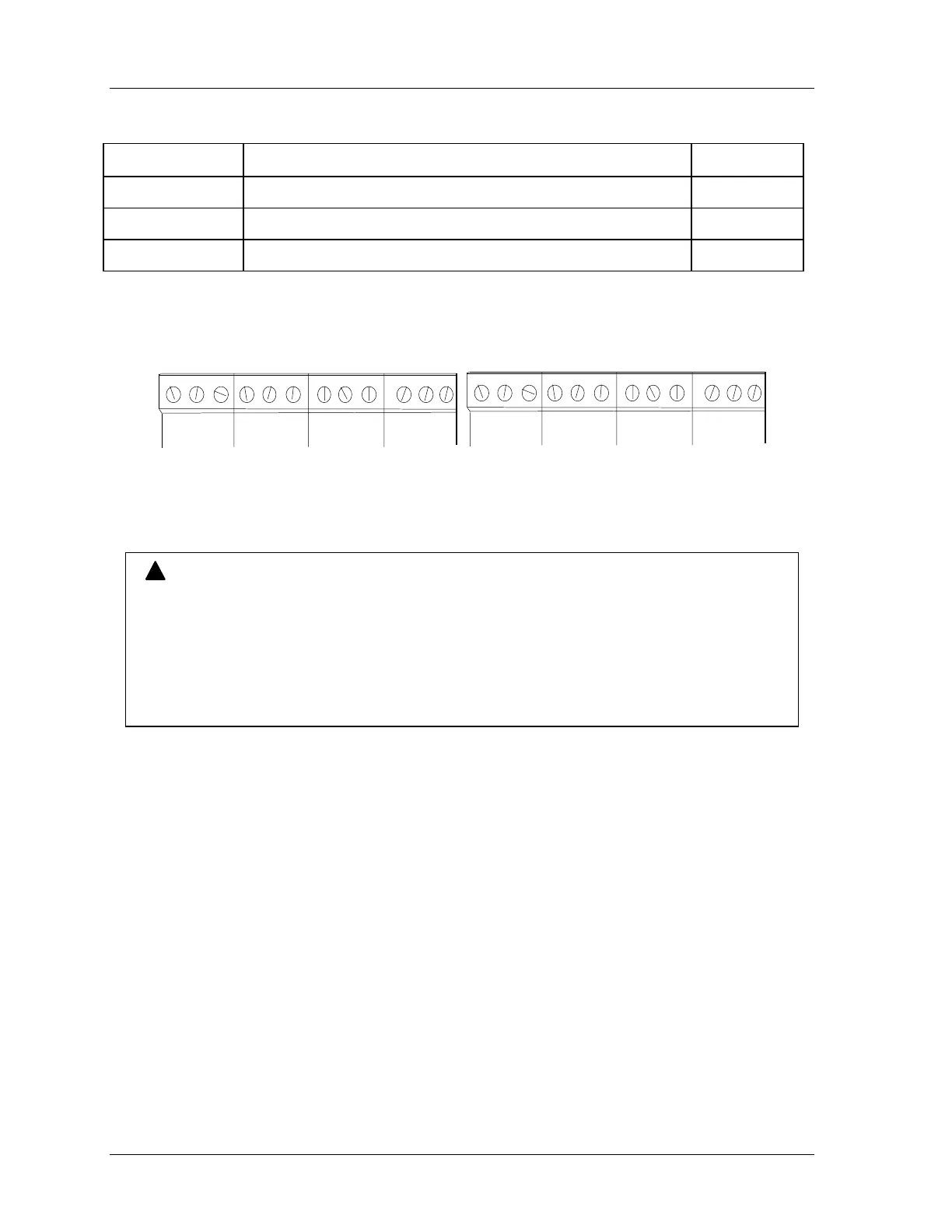
N/C C N/O
CHAN 5
N/C C N/O
CHAN 6
N/C C N/O
CHAN 7
N/C C N/O
CHAN 8
TB303
N/C C N/O
CHAN 1
N/C C N/O
CHAN 2
N/C C N/O
CHAN 3
N/C C N/O
CHAN 4
TB302
Figure 2 - 24. Connector TB302 and TB303 for Wiring Relays to Equipment
NING
!
RELAY REMAINS ENERGIZED DUE TO INCORRECT SUPPRESSOR INSTALLATION
Ensure that suppressors are correctly installed. They must not be installed across the relay
contacts inside the cam outputs enclosure. If a suppressor is installed across the relay
contacts and it fails shorted, the equipment controlled by that relay will remain energized all
the time.
Failure to comply with these instructions could result in death or serious injury.
10. You must install arc suppressors across each inductive load (motors, relays, coils, etc.)
that is connected to an output relay. Suppressors are supplied with each relay. The
suppressors reduce electrical noise and will extend the life of the relays. Find the
suppressors supplied with the modules.
11. Install the suppressors across the load and as close to the load as possible. Attach
suppressors by connecting leads across existing terminals or junction points. See the
following illustration for the correct way to install them.
 Loading...