365-575-102 Detailed Level Procedure: DLP-512
Issue 8.0, July 2002 Page 7 of 14
received power is within ranges specified.
OC-3/OC-12 LBO Selection
26. Choose the appropriate LBO from Table C.
27. Align the buildout with the slot in the buildout block, push in, and rotate clock-
wise until locked into position. Refer to the appropriate Figures (3, 4, or 5) for
the specific buildout type.
28.
IS-3 LBO Selection
NOTE:
For interconnection between an IS-3 (LAA5 or 21D/21D-U/22D-U) and an
OC-3 or circuit pack, multi-mode fiber must be used on the IS-3 transmit,
and multi-mode or single-mode can be used on the OC-3 transmit as
follows:
29. The IS-3 circuit pack uses multi-mode fiber only with a 2000 foot maximum
distance. Zero-dB multi-mode attenuators should always be used when con-
necting IS-3 circuit packs.
Table F – LBO Selection for LAA10/T939A (MM or SM fibers)
Measured Received Power in
dBm at FT-2000
UseOpticalLBOValueat
Transmit
0to-20.0dBm 7.1dB
-20.1 to -34.0 dBm 0 dB
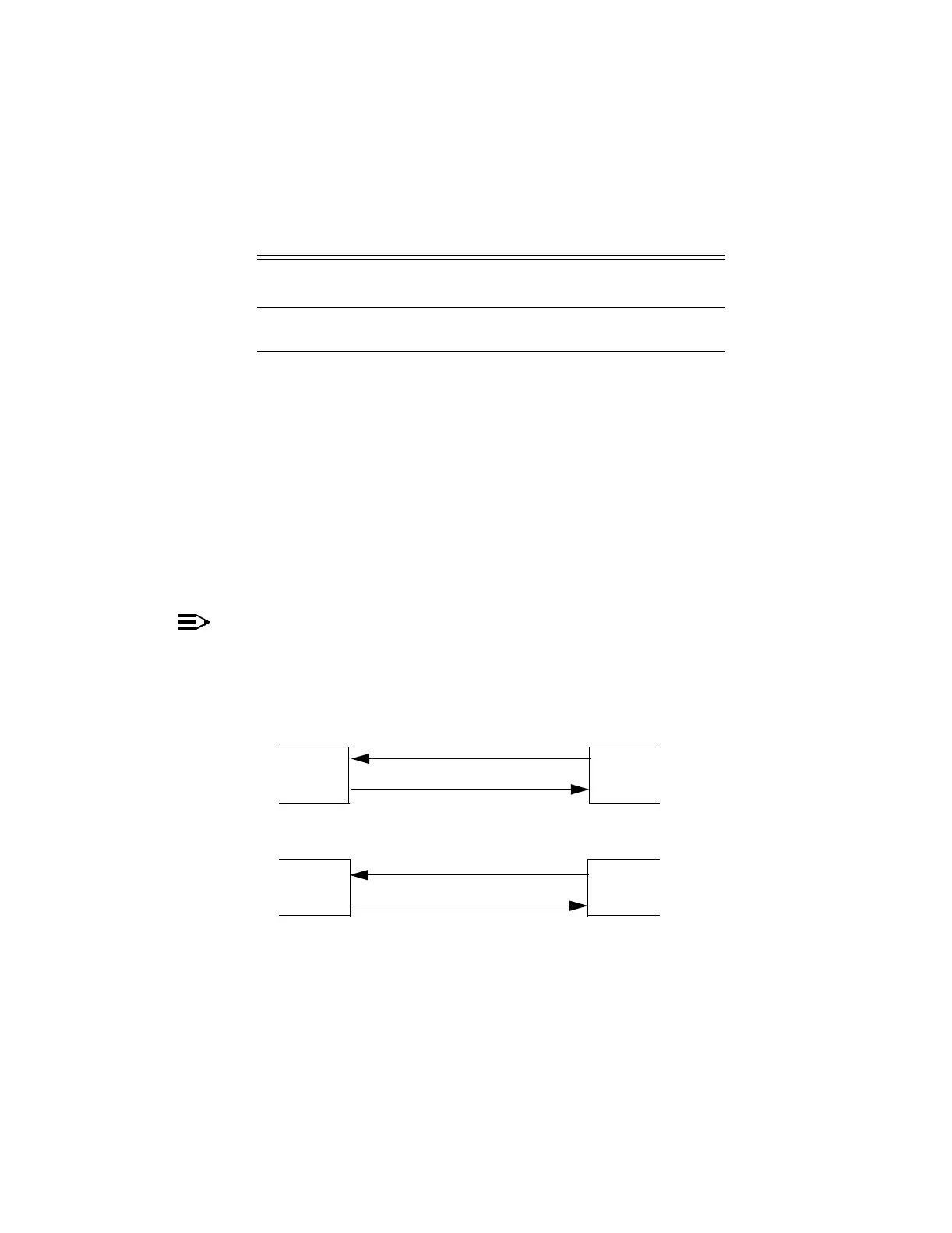
IS-3
IS-3
IS-3
OC-3
SM/MM
MM
MM
MM