DLP-550: Detailed Level Procedure 365-575-102
Page 2 of 16 Issue 8.0, July 2002
• Power line filter module
— For each feeder there is one module containing all of the filter compo-
nents as captive parts of the module.
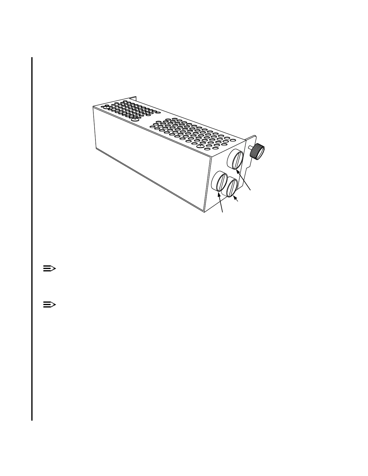
Figure 2 – Power Line Filter Module
NOTE:
Some modules have a fourth connector for a sensor lead. All modules have the
three connectors shown above.
NOTE:
A-Bays, E-Bays, and R-Bays almost always have power line filter assemblies
(Figure 1) and D-Bays almost always have power line filter modules (Figure 2).
Equipment required:
• Correct replacement power line filter for the affected shelf.
• Static ground wrist strap.
• Phillips-head or flat-blade screw driver, depending on the type of
screws on the User Panel.
• Pliers or other appropriate tool to remove power leads. Ratchet with
3/8” deep socket recommended to loosen the nuts on the capacitors.
• Flashlight.
-48V
FL
-48VR
n
-ft2
-
1