365-575-102 Detailed Level Procedure: DLP-550
Issue 8.0, July 2002 Page 11 of 16
16. Did the alarm clear in approximately five minutes?
If NO, call your next level of support.
If YES,
STOP! YOU HAVE COMPLETED THIS PROCEDURE.
NOTE:
The E10-E9 pair is bundled with the thin black lead that goes to P2.
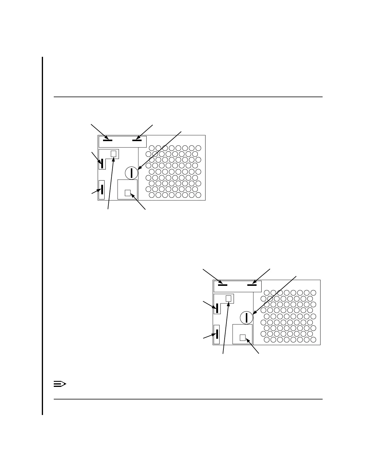
Figure 5 – Power Connections for Power Line Filter Assembly
Red Lead to E6
Black Lead to E9
Black Lead to E7
Set Screw
Blue and White Lead to P1Black Lead To P2
Red Lead to E10
nc-ft2000-021
Feeder A Connections
Grey Lead to E6
Grey With Black
Stripe Lead to E9
Grey With Black Stripe
Lead to E7
Set Screw
Blue And White Lead to P1Black Lead To P2
Grey Lead to E10
nc-ft2000-022
Feeder B Connections