365-575-102 Detailed Level Procedure: DLP-550
Issue 8.0, July 2002 Page 13 of 16
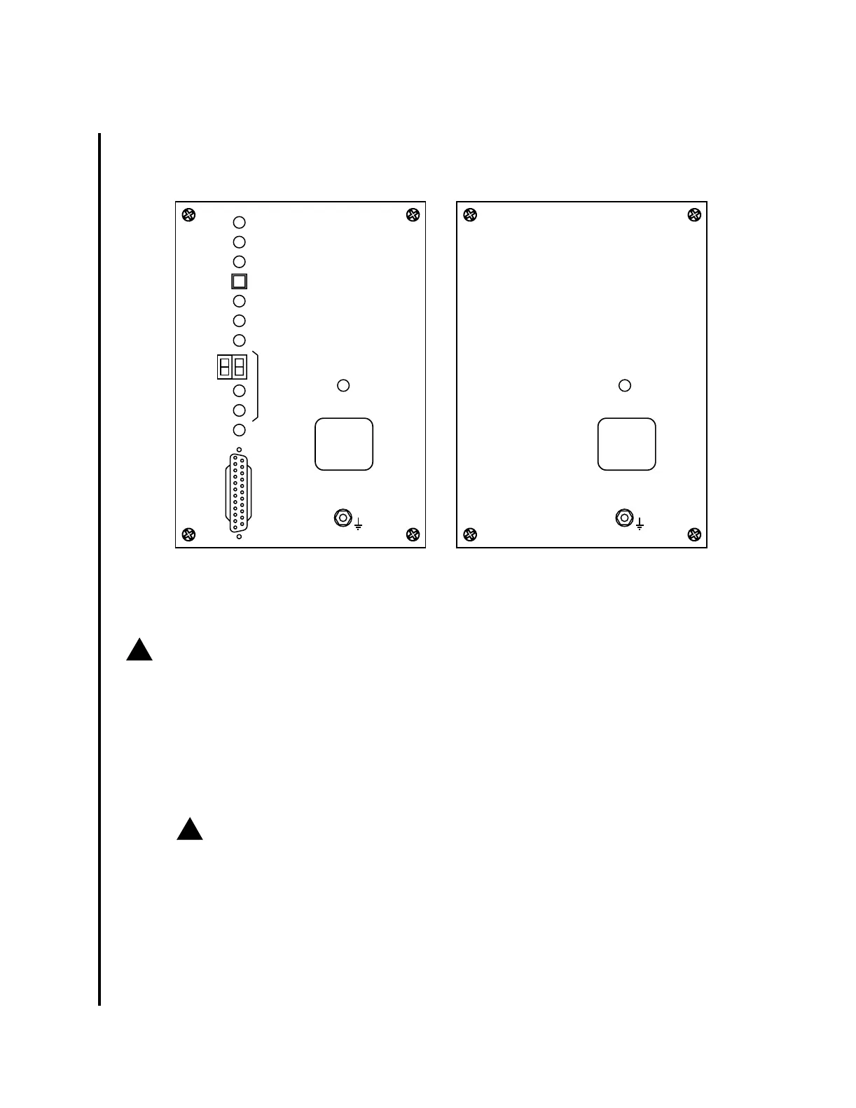
6. Notice that this exposes the four screws on the corners of the User Panel, sim-
ilar to one of the panels depicted in the following figure.
7.
!
CAUTION:
DO NOT ALLOW the screws to fall into the bay.
Remove the four corner screws from the User Panel.
8. Set the User Panel aside, being careful not to short out any of the electrical
connections on the back of the panel.
9.
!
CAUTION:
To avoid service interruption, it is essential to identify which module is
defective.
Use the color coding of the power leads to locate the defective power line filter
module for the shelf and feeder.
Reference: Figure 6 on page 15.
10.
USE
CIT
CIT
(DCE)
W
LINE
LOCTR
NE
ACTY
FE
ACTY
MN
ABN
ACO/
LOCTR
ESD WRIST
STRAP GROUND
PWR
ON
MJ
E
CR
nc-ft2000-028
ESD WRIST
STRAP GROUND
PWR
ON
LINE
NO. = 1W
LINE
NO. = 1E
LINE
NO. = 1W
LINE
NO. = 1E