Platform Descriptions
Issue 8.0 July 2002
3-55
Except for power, all cabling entering the interconnection panel is connectorized
with the following industry standard connectors:
■ BNC connectors: The BNC connectors are used on all cables for
electrical low-speed interfaces.
■ D-subminiature connectors: The D-subminiature connectors are used
on all cables for the operation system and central office interfaces.
The power cables are connected to radio frequency (RF) filters on the
interconnection panel using push-on type connectors.
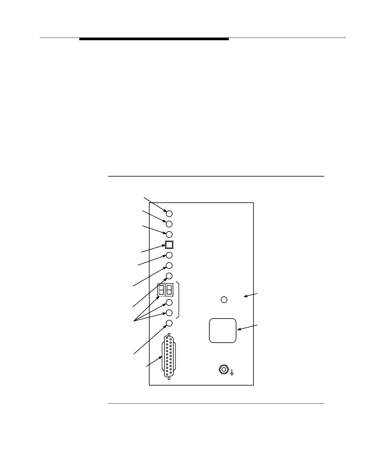
The user panel (Figure 3-30) provides −48 V power filters, a power on (PWR ON)
LED, an electrostatic discharge jack, and system level information. For more
information about the user panel, refer to Volume I, Section 6, "Operations
Interfaces."
Figure 3-30. User Panel (Enhanced)
USE
CIT
Line
Locator
Use CIT
CIT
(DCE)
STRAP GROUND
W
CIT Connector
ACTY
LINE
LOCTR
Near-End
Activity
Far-End
Activity
NE
ACTY
FE
Abnormal
MN
ABN
ACO/
LOCTR
ESD WRIST
Pushbutton
PWR
ON
MJ
Minor Alarm
E
Identification
Label
CR
Critical Alarm
Major Alarm
Line Locator
Line
LINE
Alarm Cutoff/
NO. = 1W
-48 V Power On
LINE
NO. = 1E