2D-6 - ELECTRICAL 90-824052R3 JUNE 2002
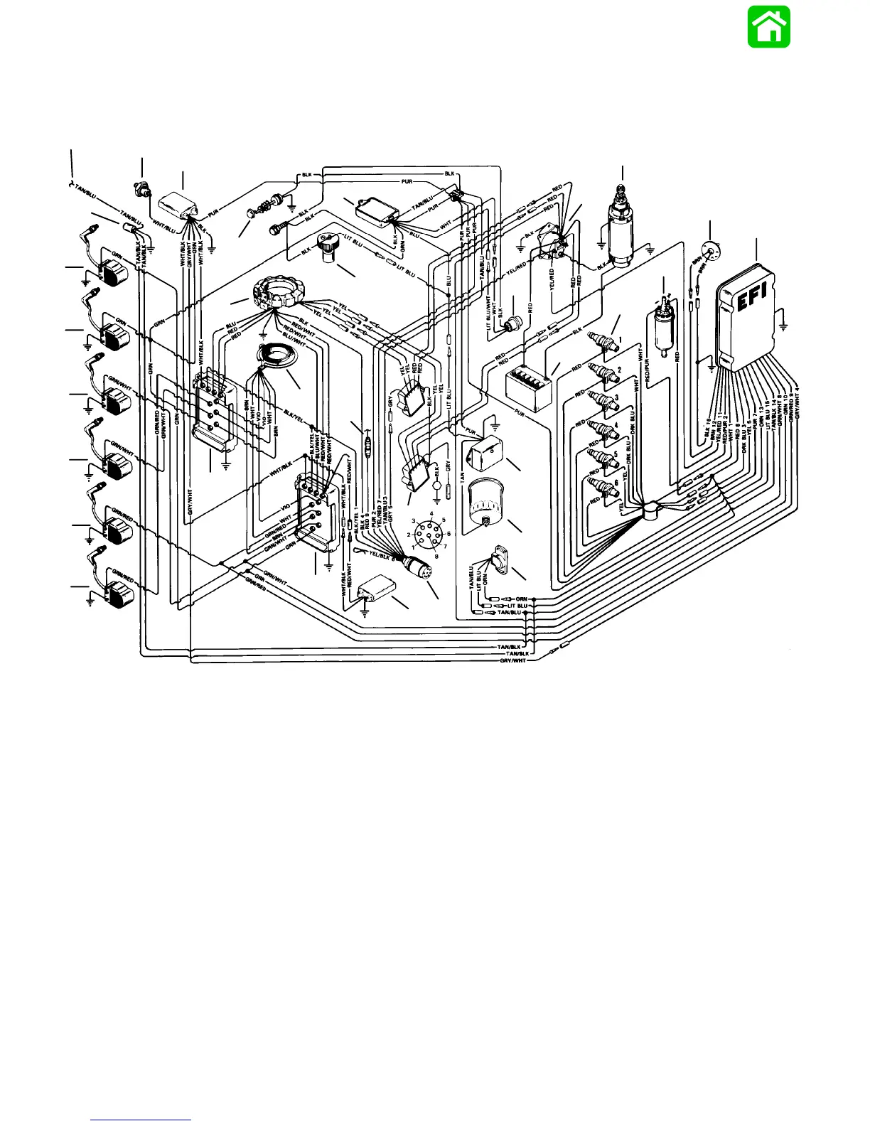
Wiring Diagram 200 EFI
BLK = BLACK
BLU = BLUE
BRN = BROWN
GRY = GRAY
GRN = GREEN
PUR = PURPLE
RED = RED
TAN = TAN
VIO = VIOLET
WHT = WHITE
YEL = YELLOW
54353
1
2
3
45
6
7
8
9
10
11
12
13
14
15
16
17
18
19
20
21
22
23
24
25
26
27
28
29
30
31
32
1 - Detonation Sensor
2 - Detonation Module
3 - Water Temperature Switch
4 - Warning Module
5 - Starter Solenoid
6 - Starter Motor
7 - Air Temperature Sensor
8 - Electronic Control Unit
9 - Fuel Pump
10- Injectors
11- 12 Volt Battery
12- Rotational Sensor
13- Water Sensing Warning Module
14- Water Separating Filter
15- Throttle Position Sensor
16- Idle Stabilizer
17- Engine Harness Connector
18- Voltage Regulator
19- 20 Ampere Fuse (To Trim Solenoid)
20- Outer Switch Box
21- Inner Switch Box
22- Trigger
23- Stator
24- Oil Tank Cap
25- Temperature Sensor
26- Coil # 1
27- Coil # 2
28- Coil # 3
29- Coil # 4
30- Coil # 5
31- Coil # 6
32- To Temperature Gauge

 Loading...