2A-26 - ELECTRICAL 90-824052R3 JUNE 2002
Ignition Coil Installation
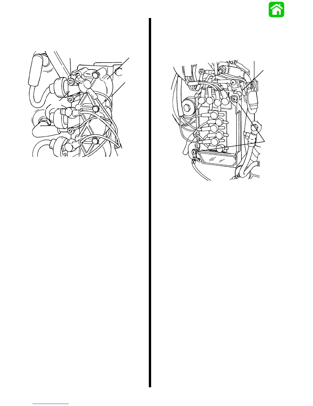
1. Place coil in coil cover and install to engine with
4 screws and nuts.
a
dc
b
51843
a - Ground Wire [Between (–) Coil Terminal and Engine
Ground]
b - Ignition Coil
c - (+) Coil Terminal
d - Coil Cover
2. Reconnect switch box wire to (+) terminal of coil
and black ground wire to (–) terminal.
3. Pull the boot back and insert spark plug lead into
coil. Caution must be taken to ensure a complete
connection of lead into coil. Form a water tight
seal between coil tower and spark plug lead
using Quicksilver Insulating Compound
(92-41669). Assemble boot over coil terminal.
SWITCH BOX(ES) REMOVAL AND
INSTALLATION
Switch Box(es) Removal
1. Remove 2 screws and lift switch boxes from
engine. (Retain round metal spacers.)
b
a
51844
a - Screws
b - Spacers
2. Disconnect wires from switch boxes.
Switch Box(es) Installation
1. Reconnect wires to proper terminals of switch
boxes. Secure a ground lead (if equipped) to
each switch box using a screw. Refer to wiring
diagram, following in this section. Wires with
yellow identification sleeve must be connected to
outer switch box. Outer switch box fires cylinders
No. 2, 4 and 6.
2. Install switch boxes to engine with 2 screws and
2 round metal spacers, as shown. Make sure that
both switch boxes are grounded to engine thru
mounting screws, spacers, and ground leads (if
equipped).

 Loading...