5B-16 - MID-SECTION 90-824052R3 JUNE 2002
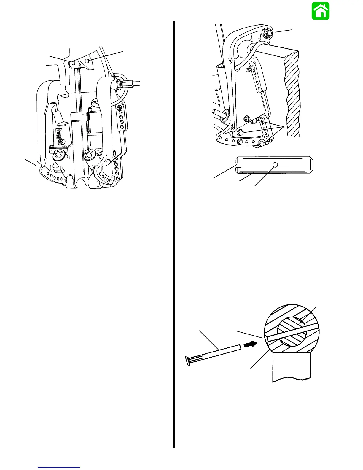
7. Drive out cross pin, push out upper swivel pin,
and remove 3 screws and washers retaining trim
system. Remove system from outboard.
51339
a
b
c
a - Cross Pin
b - Upper Swivel Pin
c - Port Transom Bracket Screws and Washers (3). Remove
to Release Trim System from Outboard.
Installation
1. Paint any exposed metal surfaces to prevent
corrosion.
2. Apply Loctite 271 to screws. Install trim system,
starboard transom bracket, and tilt tube nut.
3. Use a 12 volt power source to extend tilt ram up
to align upper swivel shaft hole and end of ram.
Connect trim motor wires [BLUE wire to POS-
ITIVE (+), BLACK wire to NEGATIVE (–)]. If ram
extends too far, retract ram by connecting
GREEN wire to POSITIVE (+).
4. Install Upper Swivel Pin with slotted end to left
(port) side of engine.
b
a
c
51375
c
a
b
a - Screw (6) Torque to 40 lb. ft. (54.0 N·m)
b - Lockwasher (6) Install one per screw
c - Tilt Tube Nut
d - Upper Swivel Pin
e - Slotted end
f - Cross hole (in line with slotted end)
IMPORTANT: Cross pin should not be reused.
Install a new pin.
5. Position slot on end of swivel shaft in line with
hole in tilt ram end. Insert a punch into tilt ram hole
to align cross hole in upper swivel shaft. Tap new
cross pin in until flush.
c
b
a
d
a - Upper Swivel Shaft (Slot is in line with cross hole)
b - Chamfered End of Hole (Faces away from transom)
c - Retaining Pin
d - Tilt Ram End
6. Connect trim motor wires to solenoids. Refer to
Wiring Diagrams in this manual. Route trim wires
as specified in this manual.

 Loading...