90-824052R3 JUNE 2002 FUEL SYSTEMS - 3D-67
Vapor Separator Installation
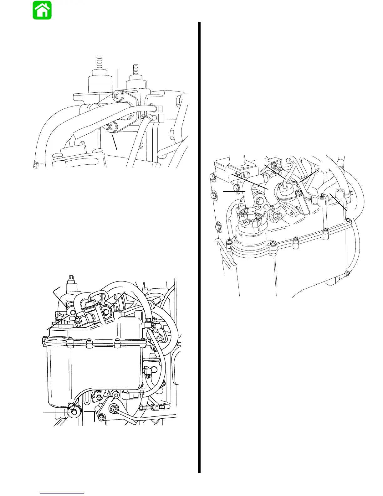
1. Secure adaptor plate to manifold with 2 screws.
Torque screws to 45 lb. in. (5.0 N·m).
55216
a
a
a - Screws [Torque to 45 lb. in. (5.0 N·m)]
NOTE: For ease of reassembly, reinstall oil reservoir
on engine BEFORE installing vapor separator.
2. Secure vapor separator to manifold with 3 screws
and washers. Torque screws to 45 lb. in. (5.0
N·m).
NOTE: Spacers are positioned between separator
and manifold at the top front and bottom attaching
screw locations.
b
b
a
a
55203
a
a - Screws [Torque to 45 lb. in. (5.0 N·m)]
b - Spacers
IMPORTANT: If fuel outlet hose from electric fuel
pump or fuel return hose from manifold to
pressure regulator was disconnected, stainless
steel hose clamps MUST BE USED to secure
connections. If outlet/return hoses are to be
replaced, replacement tubing kit (32-827694)
MUST BE INSTALLED to prevent rupturing or
leakage. DO NOT use sta-straps to secure high
pressure fuel lines as leakage will occur.
3. Connect vapor separator over flow hose between
manifold and separator.
4. Connect engine bleed hose (with white filter) to
separator.
5. Connect fuel pressure regulator hose to top fitting
on manifold.
55204
c
b
a
d
e
a - Over Flow Hose
b - Bleed Hose
c - Pressure Regulator Hose
d - Fuel Outlet Hose
e - Fuel Return Hose

 Loading...