90-824052R3 JUNE 2002 ELECTRICAL - 2D-25
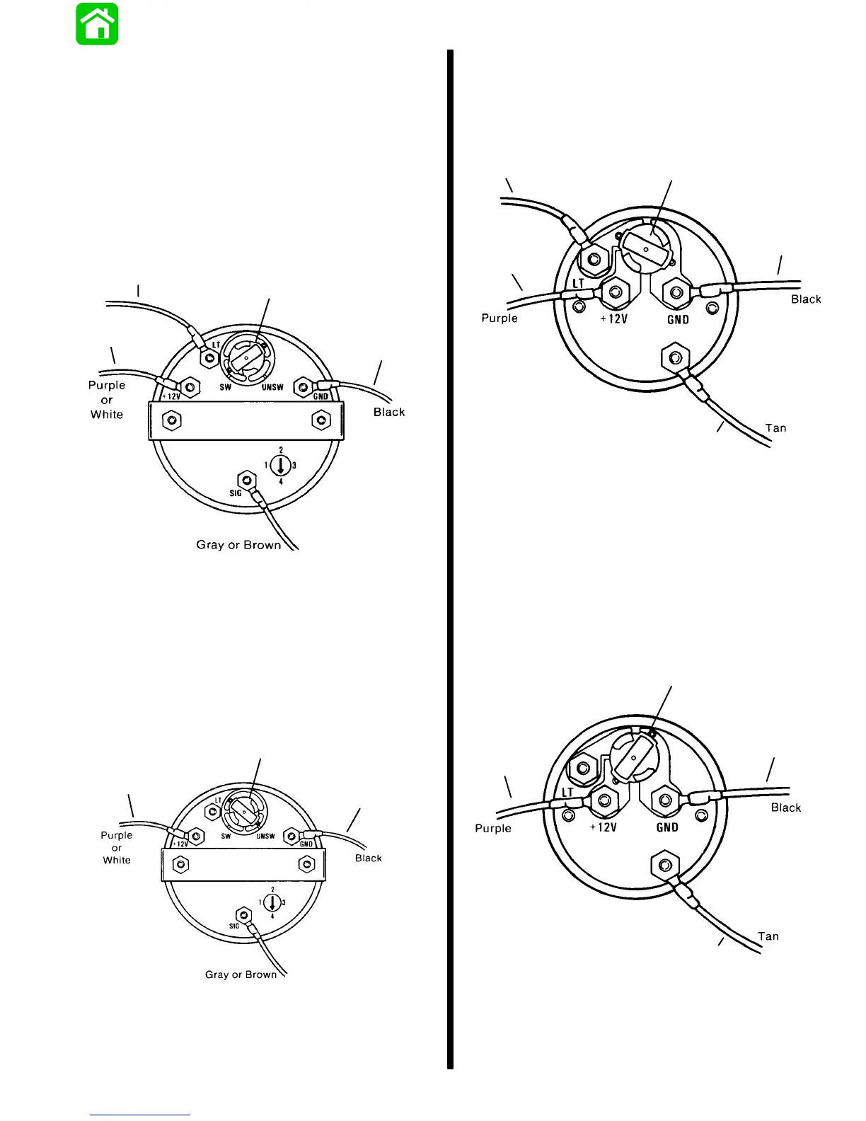
QSI Gauge Wiring Diagrams
Tachometer Wiring Diagram
Tachometer dial on back side of case must be set to
position number 4.
WIRING DIAGRAM A
Use this wiring diagram when using a separate light
switch for instrument lighting.
51106
d
a
b
c
a - Connect to + 12 Volt
b - +12 Volt Light Switch Wire
c - Position Light Bulb to the Switched Position
d - Connect to NEGATIVE (–) Ground
WIRING DIAGRAM B
Use this wiring diagram when instrument lighting is
wired directly to the ignition key switch. (Instrument
lights are on when ignition key switch is turned on.)
51106
a
b
c
a - Connect to +12 Volt
b - Position Light Bulb to the Unswitched Position
c - Connect to NEGATIVE (–) Ground
Water Temperature Gauge
WIRING DIAGRAM A
Use this wiring diagram when using a separate light
switch for instrument lighting.
SEND
a
b
c
d
e
a - Connect to + 12 Volt
b - +12 Volt Light Switch Wire
c - Position Light Bulb to the Switched Position
d - Connect to NEGATIVE (–) Ground
e - Connect to TAN Lead located at the Tachometer Recep-
tacle on Commander Side Mount Remote Control or TAN
Lead coming from Accessory Ignition/Choke Assembly.
WIRING DIAGRAM B
Use this wiring diagram when instrument lighting is
wired directly to the ignition key switch. (Instrument
lights are on when ignition key is turned on.)
51105
SEND
a
b
c
d
a - Connect to +12 Volt
b - Position Light Bulb to the Unswitched Position
c - Connect to NEGATIVE (–) Ground
d - Connect to TAN Lead located at the Tachometer Recep-
tacle on Commander Side Mount Remote Control or TAN
Lead coming from Accessory Ignition/Choke Assembly

 Loading...