5B-14 - MID-SECTION 90-824052R3 JUNE 2002
Power Trim Assembly
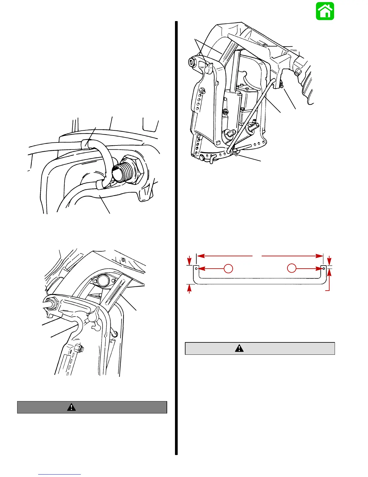
Removal and Installation
Removal
1. Remove clamps on transom bracket to free
power trim wiring.
2. Raise outboard to full “Up” position and engage
tilt lock lever.
50605
b
51377
a
a
a - Clamps
b - Tilt Lock Lever
WARNING
Failure to support outboard as shown could
result in personal injury and/or damage to
outboard or boat.
51346
b
c
c
a
a - Tilt Lock Lever
b - Support Tool
c - Retaining Clips
IMPORTANT: Support outboard as shown above
to prevent engine from tipping when power trim
retaining pin is removed.
SUPPORT TOOL
3/8 in. diameter metal rod (a used shift shaft works
well)
14”
2”
1/4”
a
a
a
a
a - Drill holes for retaining clips
METRIC CONVERSION
14 in. = 35.56 cm. 2 in. = 50.8 mm
3/8 in. = 9.5 mm. 1/4 in. = 6.35 mm.
CAUTION
Disconnect battery cables at battery before re-
moving power trim wires from solenoids.
3. Disconnect power trim wires at solenoids (BLUE,
GREEN, and BLACK) or if relay style, disconnect
(BLUE and GREEN) bullet connector harness.
4. Open filler cap and release any remaining
pressure in the system.

 Loading...