7-36 - ATTACHMENTS/CONTROL LINKAGE 90-824052R3 JUNE 2002
Fuel Connections
WARNING
Avoid serious injury or death from a gasoline fire
or explosion. All fuel lines must meet U.S. Coast
Guard approval for class “A” fuel lines.
FUEL LINE
Minimum fuel line inside diameter (I.D.) is 5/16 in.
(8mm), with separate fuel line/fuel tank pickup for
each engine.
Connecting Fuel Hose to Engine
PRODUCTION EFI MODELS
1. Connect fuel hose to fitting inside of bottom cowl
as shown. Secure with hose clamp.
2. Refer to page 7-32 for proper routing of fuel hose
thru clamp in bottom cowl.
a
b
a - Fuel Hose
b - Hose Clamp
PRODUCTION CARBURETOR MODELS
1. Connect fuel hose to “T” fitting as shown. Secure
with hose clamp.
2. Refer to page 7-32 for proper routing of fuel hose
thru clamp in bottom cowl.
b
a
a - Fuel Hose
b - Hose Clamp
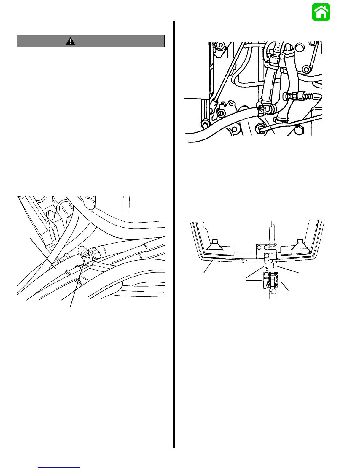
HIGH PERFORMANCE MODELS - PRO
MAX/SUPER MAGNUM
Connect inlet fuel line connector (d) from the fuel tank
to the inlet fuel connector on the front of the bottom
cowl. Hose connection is retained by the bayonet
connecting device (c).
a
b
d
c
40653
40654
a - Bottom Cowl
b - Fuel Inlet Connection on Cowl
c - Bayonet Locking Device for Fuel Connection
d - Fuel Line Connector from Fuel Tank

 Loading...