2B-10 - ELECTRICAL 90-824052R3 JUNE 2002
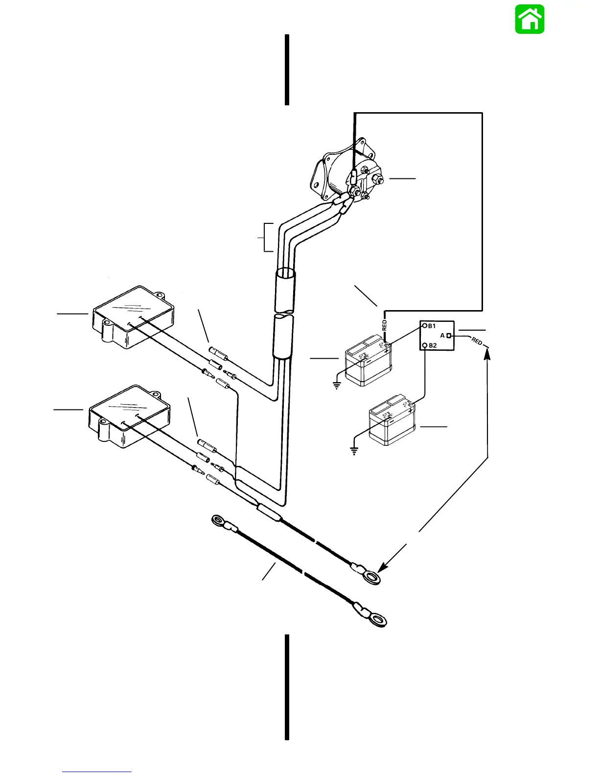
System Wired for 40 Ampere Output
to Isolator
IMPORTANT: After electrical connections are
made, coat all terminal connections using
Quicksilver Liquid Neoprene (92-25711) to avoid
corrosion.
a
b
c
d
e
f
g
h
i
k
h
j
a - Starter Solenoid
b - RED Lead to Starter Solenoid
c - Battery Isolator
d - Start Battery
e - Auxiliary Battery
f - RED pigtail Cable (from kit) to Battery Isolator
g - BLACK Cable (from kit) route from Auxiliary Battery “–”
Terminal to Engine Ground
h - Plug (from kit)
i - Lower Regulator
j - Upper Regulator
k - RED Leads – Engine Harness from Regulators to Starter
Solenoid

 Loading...