2A-24 - ELECTRICAL 90-824052R3 JUNE 2002
TRIGGER PLATE ASSEMBLY REMOVAL AND
INSTALLATION
Trigger Plate Assembly Removal
1. Remove flywheel, as outlined in “Flywheel
Removal and Installation,” preceding.
2. Remove 4 screws which secure stator assembly
to upper end cap. Lift stator off end cap and move
to the side.
3. Remove locknut that secures link rod swivel into
spark advance lever. Pull link rod out of lever.
4. Remove 2 screws and lift outer switch box from
inner switch box. (Retain round metal spacers.)
5. Disconnect all trigger leads from their respective
terminals. Cut sta-strap and remove trigger plate
assembly from engine.
6. If trigger assembly is faulty, remove and retain
link rod swivel from trigger.
a
b
51844
a - Trigger
b - Link Rod Swivel
Trigger Plate Assembly Installation
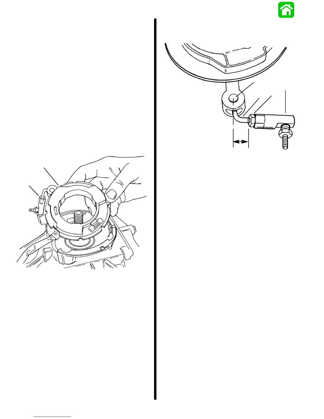
1. If link rod swivel was disassembled or removed,
reassemble to trigger as shown.
b
c
d
e
a
51840
a - Retain This [11/16 in. (17.5 mm)] Dimension
b - Pivot
c - Link Rod
d - Hex Nut
e - Ball Joint

 Loading...