90-824052R3 JUNE 2002 ELECTRICAL - 2A-23
STATOR ASSEMBLY REMOVAL AND
INSTALLATION
Stator Assembly Removal
1. Remove flywheel, as outlined in “Flywheel
Removal and Installation,” preceding.
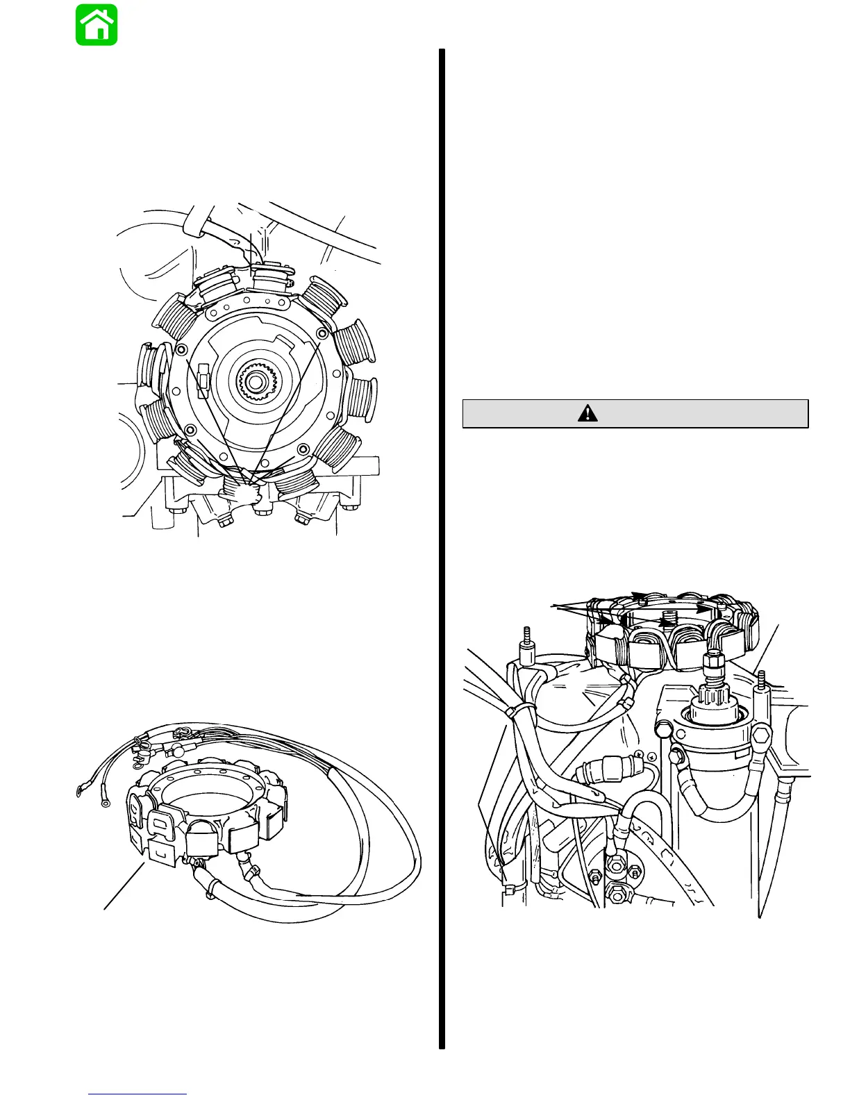
2. Remove 4 screws which secure stator to the
upper end cap.
b
51797
a
a - Stator Attaching Screws
b - Stator
3. Remove 2 screws and lift outer switch box from
inner switch box. (Retain round metal spacers.)
4. Disconnect all stator leads from their respective
terminals, cut sta-strap(s) and remove stator
assembly from engine.
a
51797
a - Stator Assembly
Stator Assembly Installation
1. Clean stator attaching screw threads with Loctite
Primer T (92-59327--1 ) and apply Loctite 271
(obtain locally). Install stator assembly in position
on upper end cap and secure with attaching
screws. Torque screws to 50 Ib. in. (5.5 N m).
2. Reconnect wires to proper terminals of voltage
regulator/rectifier and switch boxes. Reconnect
ground lead to ground. Refer to wiring diagram,
following in this section. Wires with yellow identifi-
cation sleeve must be connected to outer switch
box.
3. Install switch boxes to engine with 2 screws and
2 round metal spacers. Refer to switch box(es)
removal and installation (see “Table of Con-
tents”). Make sure that both switch boxes are
grounded to engine thru mounting screws and
spacers.
CAUTION
Switch boxes must be grounded to engine before
cranking engine, or switch boxes will be
damaged.
4. Route stator wiring harness as shown. Secure
with sta-strap and clamp.
5. Reinstall flywheel, as outlined in “Flywheel
Removal and Installation,” preceding.
a
c
b
51797
a - Stator Attaching Screws with Lock washers (4)
b - Stator Harness (Route as Shown; Wires with Yellow
Sleeves Connected to Outer Switch Box)
c - Sta-Strap

 Loading...