3D-66 - FUEL SYSTEMS 90-824052R3 JUNE 2002
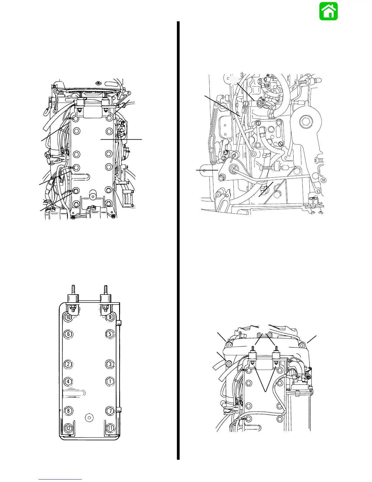
3. Secure induction manifold assembly to engine
with screws. Torque screws to 90 Ib. in. (10.0
N·m) using torque sequence shown below.
NOTE: Remove M8 x 1.25 x 38mm long bolts used
for reassembly and install remaining screws. Install
ground wires to proper location.
a
c
c
b
c
55210
a - Manifold
b - Screws [Torque to 90 lb. in. (10.0 N·m)]
c - Ground Wires
Cover Screw Torque Sequence
IMPORTANT: Before connecting oil pump control
rod verify pump quadrant is rotated to the
clockwise of center.
4. Connect oil injection link rod to injector arm.
5. Connect throttle link rod to throttle cam.
c
b
a
d
55213
a - Throttle Link Rod
b - Throttle Cam
c - Oil Injection Link Rod
d - Oil Injection Arm
Oil Reservoir Installation
1. Install oil reservoir to engine. Connect hose to
fitting and secure with hose clamp.
2. Install studs, nuts, and mounting bracket. Secure
reservoir using screws. Torque screws to 25 lb.
in. (3.0 N·m).
b
c
c
c
a
55201
a - Studs
b - Nuts
c - Screws [Torque 25 lb. in. (3.0 N·m)]

 Loading...