90-824052R3 JUNE 2002 FUEL SYSTEMS - 3D-51
Vapor Separator Reassembly
VAPOR SEPARATOR FLOAT INSTALLATION
1. Attach float needle to float arm.
2. Guide float/needle assembly under float drop
limit bracket and place needle into seat.
3. Slide pivot pin through float arms.
4. Verify float’s freedom of movement through pivot
range.
55207
a
c
d
b
a - Float
b - Float Needle (Hidden)
c - Float Drop Limit Bracket
d - Pivot Pin
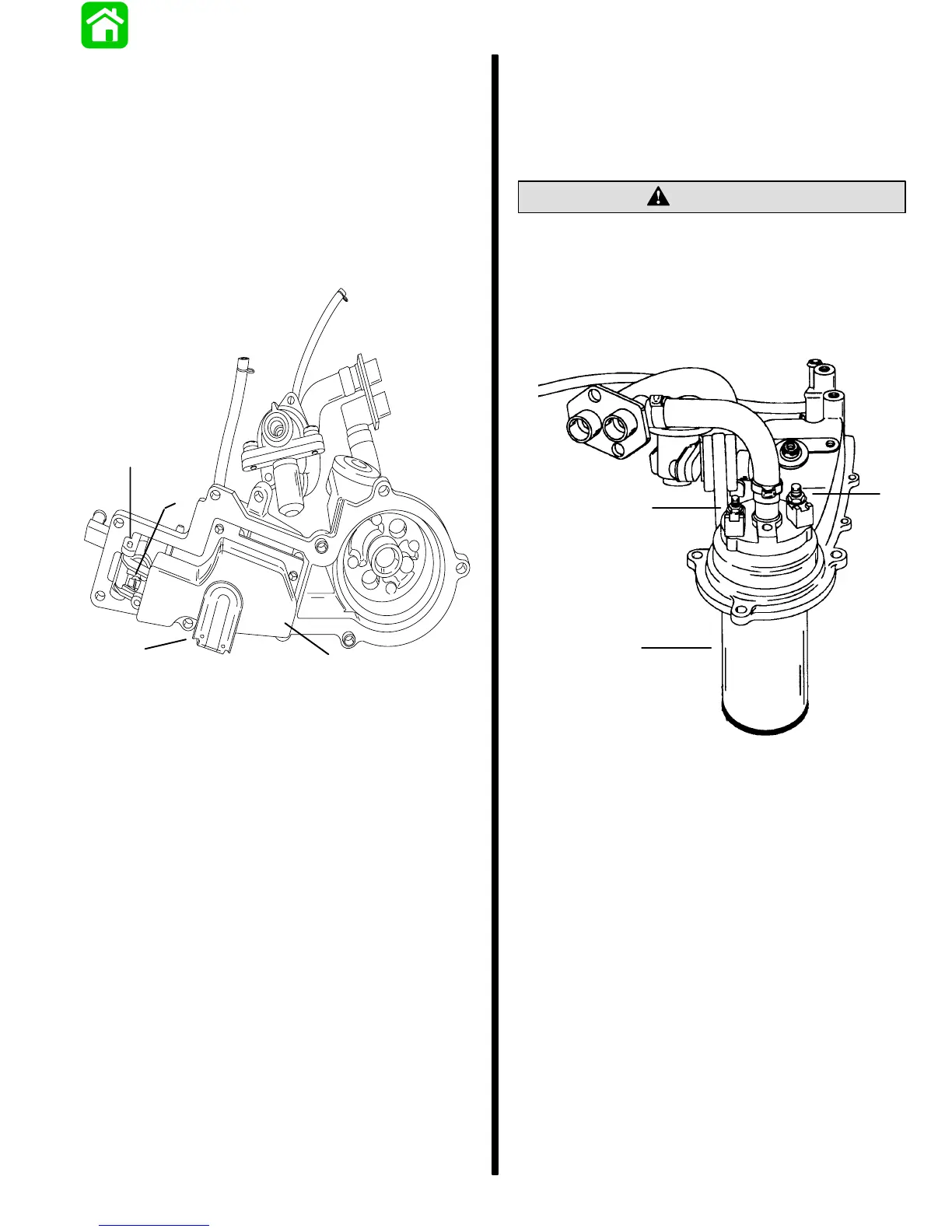
ELECTRIC FUEL PUMP INSTALLATION
1. Slide fuel pump into separator cover.
NOTE: Fuel pump electrical studs are different
diameters. Pump will install properly into cover only
one way.
CAUTION
DO NOT over torque fuel pump POSITIVE and
NEGATIVE attaching nuts as damage to fuel
pump will result.
2. Secure pump to cover with 2 nuts. Torque POS-
ITIVE nut to 6 lb. in. (0.7 N·m). Torque NEGATIVE
nut to 8 lb. in. (0.9 N·m).
c
b
a
a - Electric Pump
b - POSITIVE (+) Stud (Small Diameter)
c - NEGATIVE (–) Stud (Large Diameter)

 Loading...