3C-34 - FUEL SYSTEMS 90-824052R3 JUNE 2002
STEP 3: Connect a jumper wire between the
metal case of ECM and a good engine
ground.
WARNING
If a serious leak is present in the induction man-
ifold, fuel may spray out of bad seal. Have clean
up rags available to remove excess fuel from
components.
STEP 4: Place emergency stop switch in OFF
position to prevent engine from starting. If
boat is not equipped with a emergency
stop switch, connect a jumper lead from
the BLACK/YELLOW terminal on the
switch box to engine ground.
STEP 5: Connect remote starter Quicksilver
(91-52024A1) to negative terminal of
electric fuel pump and a good engine
ground. Depress remote start switch,
pump will operate as long as switch is
depressed.
WARNING
Do not operate pump for more than 20 seconds
continuously.
STEP 6: Look for leak points on induction man-
ifold while depressing remote starter
switch.
Results: If no leaks are present, replace cover and
gasket using normal length screws.
If fuel leak is present between sealing surfaces,
rebuild system using new O-rings.
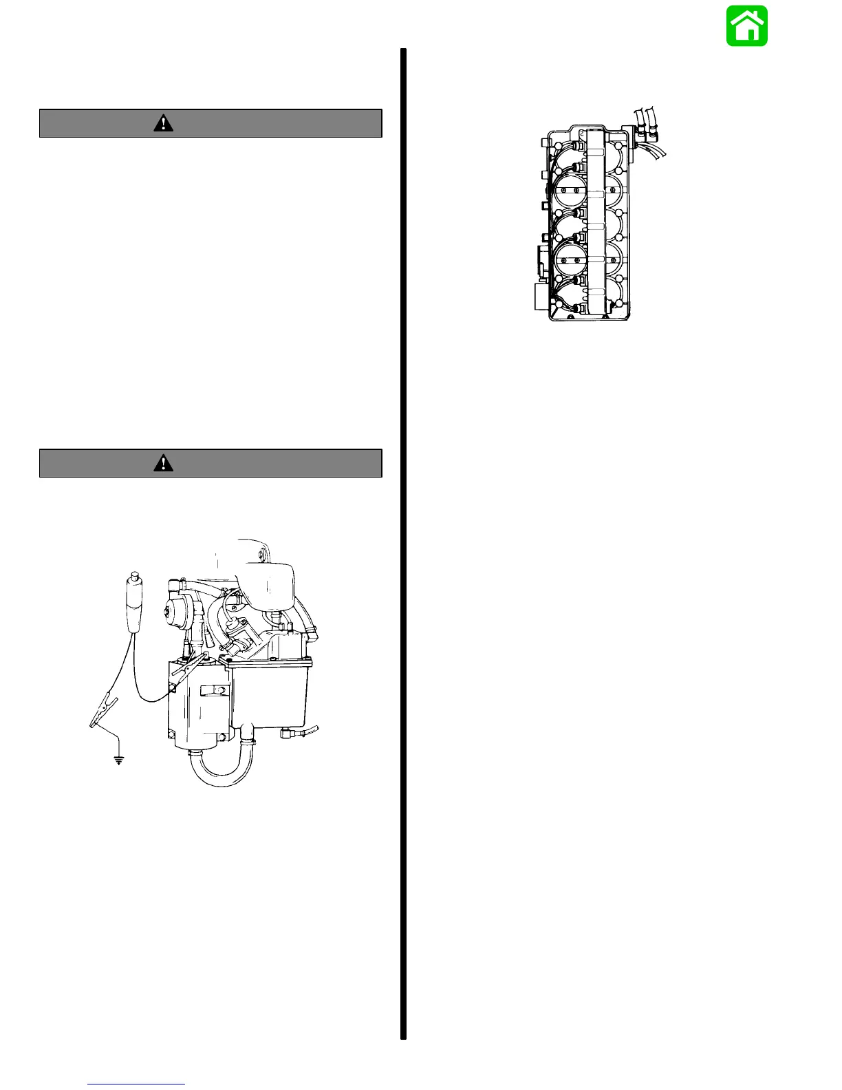
Air Temperature Sensor Test
Purpose: This test eliminates possibilities of im-
proper fuel delivery related to air temperature
sensor.
Procedure: STEP 1: Disconnect and remove Air
Temperature Sensor from induction man-
ifold.
STEP 2: Connect digital meter set at “20K scale”
(from EFI Tester P/N 91-11001A2) to
leads of sensor.
STEP 3: Place sensor in ice water while monitor-
ing meter reading. Use graph (following
page) for reference.

 Loading...