3D-54 - FUEL SYSTEMS 90-824052R3 JUNE 2002
NOTE: For ease of reassembly, reinstall oil reservoir
on engine BEFORE installing vapor separator.
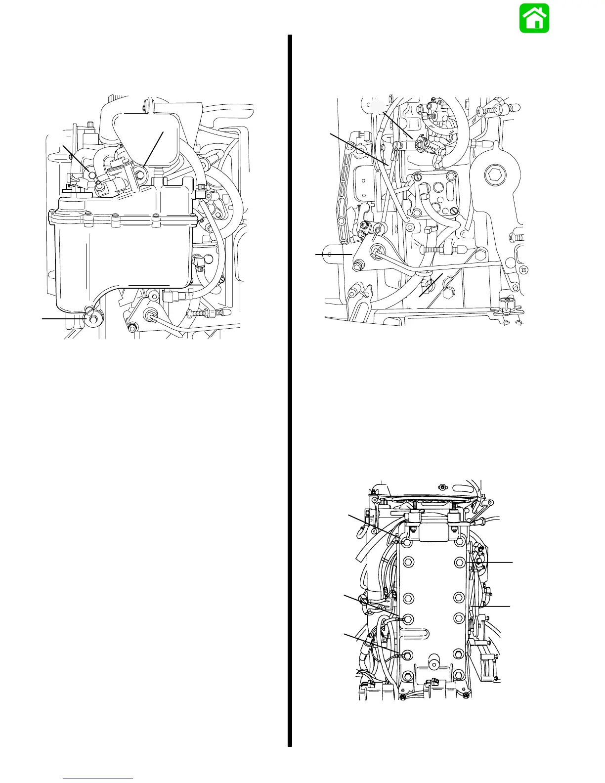
7. Secure separator to manifold with 3 bolts and
washers. Torque bolts to 45 lb. in. (5.0 N·m).
55176
a
a
a
a - Bolts and Washers [Torque bolts to 45 lb. in. (5.0 N·m)]
Manifold Removal
1. Disconnect throttle link rod from throttle cam.
2. Disconnect oil injection link rod from injector arm.
c
b
a
d
55213
a - Throttle Link Rod
b - Throttle Cam
c - Oil Injection Link Rod
d - Injector Arm
3. Identify location of 3 ground wires for reassembly
purposes.
4. Remove 12 screws securing manifold cover to
manifold.
5. Remove manifold cover.
55210
c
a
a
a
b
a - Ground Wires
b - Screws (12)
c - Manifold Cover

 Loading...