2A-14 - ELECTRICAL 90-824052R3 JUNE 2002
2-B. Check ignition switch/wiring, as follows:
WARNING
DANGER--HIGH VOLTAGE SHOCK/FIRE HAZ-
ARD. STAY CLEAR OF SPARK PLUG LEADS. To
assure personal safety, each individual spark
plug lead should be grounded to the engine.
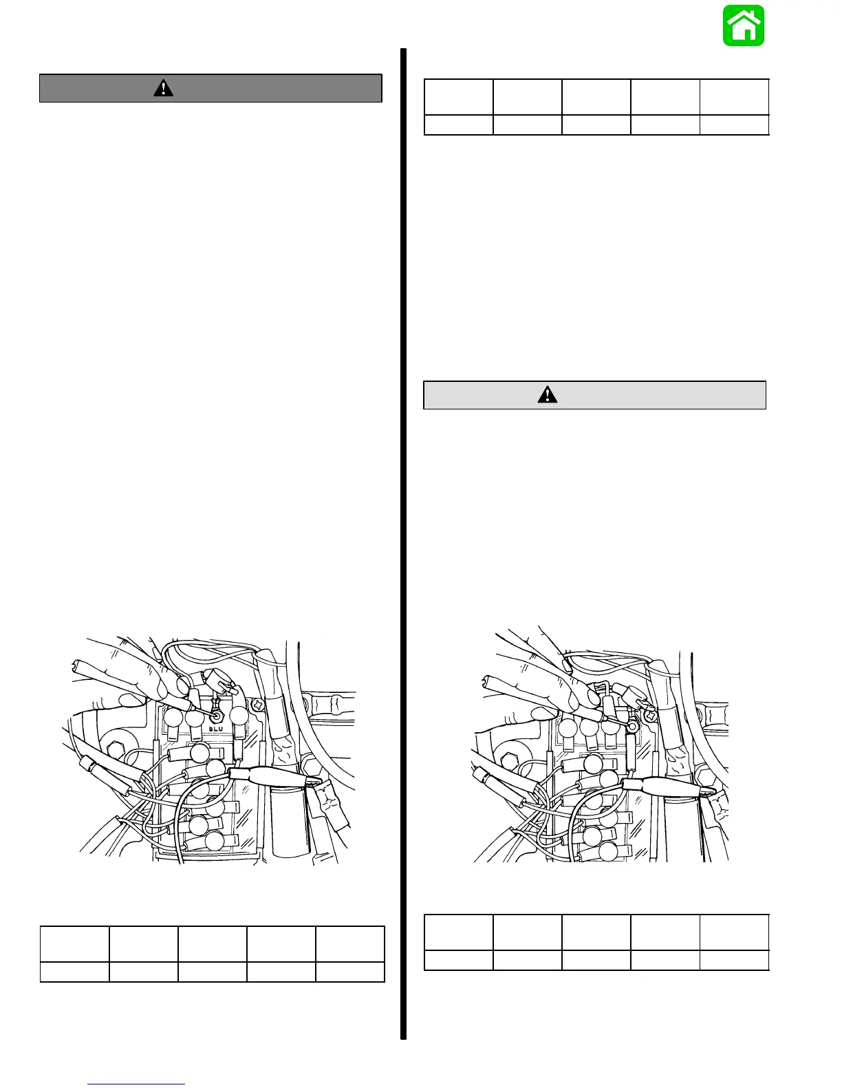
1. To prevent engine from starting, remove spark
plug leads from ALL spark plugs, then ground
ALL spark plug leads to the engine.
2. Remove ignition switch and mercury switch lead
wire(s) from switch box(es) [lead wire(s) are
connected to ORANGE switch box terminal(s) on
EARLY model engines -- BLACK/YELLOW
switch box terminal(s) on LATER model
engines].
NOTE: Be sure to disconnect ignition switch lead
wire from both switch boxes.
3. With ignition switch and mercury switch lead
wire(s) ISOLATED (removed in preceding Step
2), repeat check in Step 2-A.
a. If reading still is BELOW specification, pro-
ceed with Step 3-A.
b. If reading now is WITHIN specification, either
the ignition switch, mercury switch, lanyard
stop switch or wiring is bad.
3-A. Check stator low speed and high speed in-
put to switch box. (See Test Chart, following.)
NOTE: This is INNER switch box.
51838
STATOR LOW SPEED TEST
DVA RED DVA BLK 400 RPM 1000
RPM
3000
RPM
BLUE GROUND 100 - 265 195 - 265 255 - 345
STATOR HIGH SPEED TEST
DVA RED DVA BLK 400 RPM 1000
RPM
3000
RPM
RED GROUND 25 - 50 120 - 160 230 - 320
1. If either the low speed or high speed reading to
switch box is BELOW specification, stator or
switch box is bad (test stator as outlined in Out-
board Service Manual; if stator checks to specifi-
cation replace switch box and repeat check).
IMPORTANT: If engine is equipped with an Idle
Speed Stabilizer and/or High Speed Spark Ad-
vance, disconnect and isolate both leads from
switch box and repeat check to rule out possible
stabilizer/spark advance malfunction.
2. If both the low speed and high speed readings are
WITHIN specification, proceed with Step 4-A.
CAUTION
On V-6 models, OUTER switch box must be re-
moved from engine (which also loosens INNER
switch box) to gain access to INNER switch box.
BEFORE checking stator input to INNER switch
box, a GROUND LEAD MUST BE INSTALLED BE-
TWEEN BOTH switch boxes (INNER and OUTER)
and engine to prevent possible damage to igni-
tion components and/or test equipment.
4-A. Check stator low speed and high speed
input to OUTER switch box. (See Test Chart,
following.)
51830
STATOR LOW SPEED TEST
DVA RED DVA BLK 400 RPM 1000
RPM
3000
RPM
BLU/WHT GROUND 100 - 265 195 - 265 255 - 345

 Loading...