1D-12 - IMPORTANT INFORMATION 90-824052R3 JUNE 2002
Bleeding Air from Oil Injection Pump
and Oil Injection Outlet Hose
BLEEDING AIR FROM OIL INJECTION PUMP
With engine not running, place a shop towel below
the oil injection pump. Loosen bleed screw three to
four turns and allow oil to flow from bleed hole. Re-
tighten bleed screw. This procedure allows the pump
to fill with oil.
BLEEDING AIR FROM OIL INJECTION PUMP
OUTLET HOSE
Any air bubbles in outlet hose in most cases will be
purged out of the system during operation of the
engine.
NOTE: If air bubbles persist, they can be purged out
of the hose by removing link rod and rotating the
pump arm full clockwise while operating engine at
1000 to 1500 RPM: If necessary, gently pinch the fuel
line between the remote fuel line connector and the
oil injection pump “Tee” fitting. This will cause the fuel
pump to provide a partial vacuum which will aid in re-
moval of the air. Reinstall link rod.
a
b
d
c
50047
a - Bleed Screw
b - Outlet Hose
c - Link Rod
d - Pump Arm
Adjusting Oil Injection Pump
When throttle linkage is at idle position, alignment
mark on oil injection arm should be in-line with mark
on casting as shown. If necessary, adjust link rod.
50060
a
b
c
a - Link Rod
b - Alignment Mark
c - Casting Mark
Propeller Selection
Refer to “Quicksilver Accessory Guide” for a com-
plete list of available propellers.
For best all around performance from your outboard/
boat combination, select a propeller that allows the
engine to operate in the upper half of the recom-
mended full throttle RPM range with the boat
normally loaded (refer to Specifications in the
Operators Manual). This RPM range allows for
better acceleration while maintaining maximum boat
speed.
Check full-throttle RPM using an accurate tachome-
ter with the engine trimmed out to a balanced steer-
ing condition (steering effort equal in both directions)
without causing the propeller to “break loose.”
Propeller Installation
WARNING
When the propeller shaft is rotated and the en-
gine is in gear, there is the possibility for the en-
gine to crank over and start. To prevent this type
of accidental engine starting and possible seri-
ous injury caused from being struck by a rotating
propeller, always set the remote control into neu-
tral and remove spark plug leads when you are
servicing the propeller.
NOTE: To prevent the propeller hub from corroding
and seizing to the propeller shaft, especially in salt
water, always apply a coat of Quicksilver
Anti-Corrosion Grease to the entire shaft.
1. Set the remote control into neutral position.
2. Remove leads from spark plugs to prevent
engine from starting.
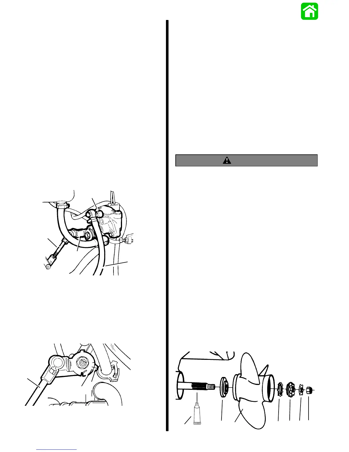
3. Coat the propeller shaft with Quicksilver Anti-
Corrosion Grease (g).
4. Install thrust washer (a), propeller (b), continuity
washer (c), thrust hub (d), tab washer (e), and
self locking nut (f) onto the shaft.
5. Torque propeller nut to 55 lb. ft. (75 N·m).
6. Bend three of the tabs into the propeller hub
grooves.
g
a
b
cd
ef

 Loading...