6B-44 - LOWER UNIT 90-824052R3 JUNE 2002
8. Move driveshaft up and down to determine end
play. Total up and down movement should be
0.00″ to 0.001″ (0.025mm). There should be no
preload on the bearing and the driveshaft must
rotate freely.
NOTE: DO NOT change shims under upper bearing
cup or pinion height will be changed.
9. Maintain the shims as previously set under the
upper driveshaft bearing cup.
10. Remove the upper bearing cup retainer with tool
91-43506, and remove cup [leave upper cup
shim(s) in place].
NOTE: A 0.001
″
(.025mm) change of shims under
the lower bearing cup will result in a 0.001
″
(0.025mm) change in driveshaft end play.
11. Place driveshaft end play shim(s), determined
from step 8, into gear housing and reinstall the
lower bearing cup.
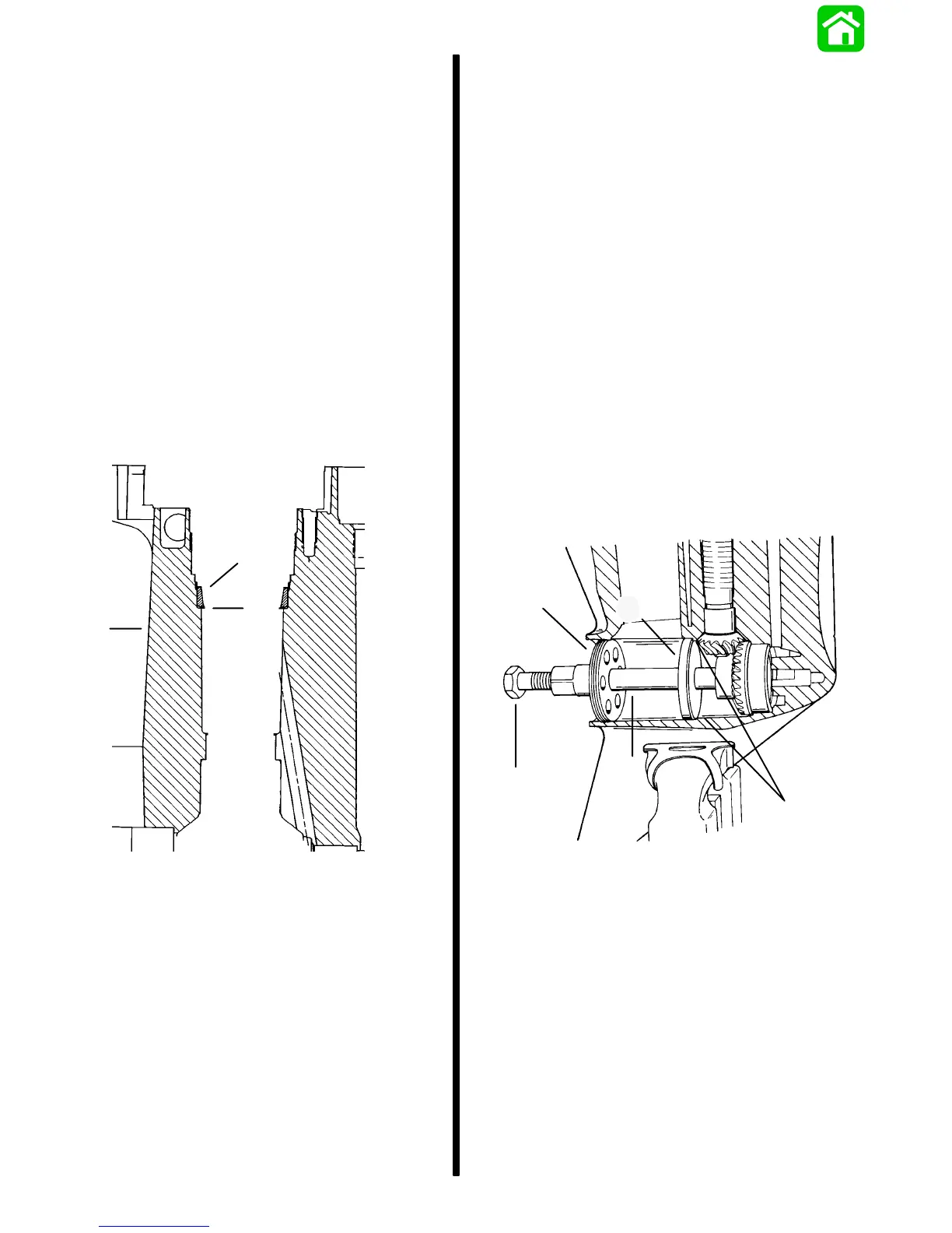
a
b
c
a - Driveshaft Housing
b - Lower Driveshaft Bearing Cup
c - Location of Driveshaft End Play Shims
12. Clean threads of driveshaft and apply Loctite
#271.
13. Apply gear oil to all bearing surfaces and install
driveshaft assembly, upper bearing cup and
retainer into the gear case. Tighten upper cup
retainer to a torque of 100 lb. ft. (135.5 N·m).
NOTE: If reverse gear backlash has not yet been
determined, do not use a new pinion nut until final
assembly.
14. Apply #271 Loctite to a NEW pinion nut and install
the pinion gear, washer and nut using procedures
detailed earlier in this section. Tighten pinion nut
to a torque of 85 lb. ft. (115 N
.
m).
15. Rotate driveshaft a few turns to verify that it turns
freely and recheck driveshaft end play.
Reverse Gear
DETERMINING REVERSE GEAR BACKLASH
NOTE: Although reverse gear backlash is not adjust-
able, it can be checked as follows:
1. Install Driver Tool (91-18605) into reverse gear
assembly.
2. Slide Pilot Ring (91-18603) over driver tool and
seat pilot ring against inner ledge in gear case.
3. Thread Retainer (91-18604) into gear case cover
nut threads.
4. Torque Screw (91-18602) to 45 Ib. in. (5.0 N·m)
against driver tool.
d
e
c
51884
b
a
a - Driver Tool (91-18605)
b - Pilot Ring (91-18603)
c - Inner Ledge
d - Retainer (91-18604)
e - Screw (91-18602) [Torque to 45 lb. in. (5.0 N·m)]
5. Thread stud adapter [from Bearing Preload Tool
(91-14311A1)] all the way onto stud.
6. Install: Backlash Indicator Tool (91-78473)
Dial Indicator Holder (91-89897)
Dial Indicator (91-58222A1)
7. Position dial indicator pointer on line marked “1”
on Backlash Indicator Tool, if gear ratio is 1.87:1
(15 teeth on pinion gear), or on line marked “2” on
Backlash Indicator Tool, if gear ratio is 2:1 (14
teeth on pinion gear).

 Loading...