1D-6 - IMPORTANT INFORMATION 90-824052R3 JUNE 2002
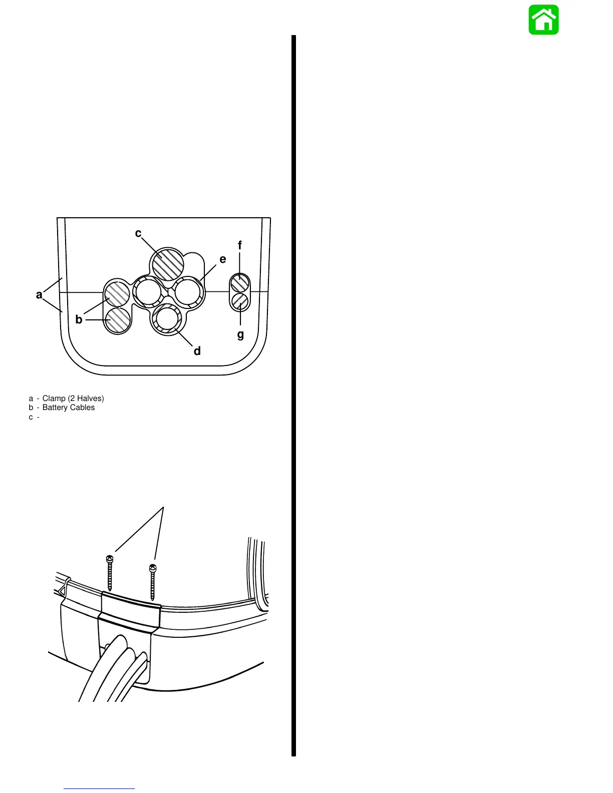
Routing Location for Wiring
and Hoses thru Clamp in
Bottom Cowl
IMPORTANT: Sufficient slack must exist in en-
gine wiring harness, battery cables, fuel hose,
and oil hoses routed between clamp and engine
attachment point, to relieve stress and prevent
hoses from being kinked or pinched.
1. Route engine wiring harness, battery cables, fuel
hose, oil hoses and control cables thru clamp in
bottom cowl at locations shown.
a
b
c
e
d
g
f
a - Clamp (2 Halves)
b - Battery Cables
c - Engine Wiring Harness
d - Fuel Hose
e - Oil Hoses
f - Throttle Cable
g - Shift Cable
2. Secure clamp halves together with 2 screws.
a
52188
a - Screws
Remote Control Installation
Refer to “Quicksilver Accessories Guide” to deter-
mine correct length of remote control cables.
IMPORTANT: Remote control cables must be cor-
rect length. Sharp bends on too-short cables re-
sult in “kinks;” too-long cables require unneces-
sary bends and/or loops. Both conditions place
extra stress on the cables.
IMPORTANT: Install control cables to remote
control and mount remote control BEFORE
attaching control cables to engine. Refer to
installation instructions included with remote
control.
Counter (Left Hand) Rotation
Outboards
IMPORTANT: Counter rotating (left hand) gear
cases can be identified by a “L” stamped into the
end of the propeller shaft.
On counter (left hand) rotation outboards, the shift
guide block moves aft for FORWARD and towards
the bow for REVERSE. This is opposite motion
compared to a standard (right hand) rotation out-
board.
The Quicksilver Commander Series Dual Engine
Console Mount Control, P/N 88688A22, is required
to shift the counter rotation outboard. The installation
instructions shipped with the control explain the pro-
cedure required to connect this control to a counter
rotation outboard.
IMPORTANT: If the counter rotation outboard is
rigged similar to a standard rotation outboard OR
if a standard rotation outboard is rigged similar
to a counter rotation outboard, the reverse gear
and bearing in the gear case must function as for-
ward gear. THE REVERSE GEAR/BEARING ARE
NOT DESIGNED TO CARRY THE SUSTAINED
LOADS THAT ARE GENERATED WHEN RUN-
NING UNDER CONSTANT HIGH RPM AND
THRUST CONDITIONS.

 Loading...