6A-56 - LOWER UNIT 90-824052R3 JUNE 2002
Installing Gear Housing to Drive
Shaft Housing
WARNING
Disconnect high tension leads from spark plugs
and remove spark plugs from engine before
installing gear housing onto driveshaft housing.
1. Tilt engine to full up position and engage the tilt
lock lever.
2. Apply a light coat of Quicksilver 2-4-C w/Teflon
Marine Lubricant onto driveshaft splines.
CAUTION
DO NOT allow lubricant on top of drive shaft.
Excess lubricant, that is trapped in clearance
space, will not allow driveshaft to fully engage
with crankshaft. Subsequently, tightening the
gear housing nuts (while excess lubricant is on
top of drive shaft) will load the
driveshaft/crankshaft and damage either or both
the powerhead and gear housing. Top of
driveshaft is to be wiped free of lubricant.
3. Apply a light coat of Quicksilver 2-4-C w/Teflon
Marine Lubricant onto shift shaft splines. (DO
NOT allow lubricant on top of shift shaft.)
4. Apply a thin bead of G.E. Silicone Sealer
(obtained locally) against the top of divider block.
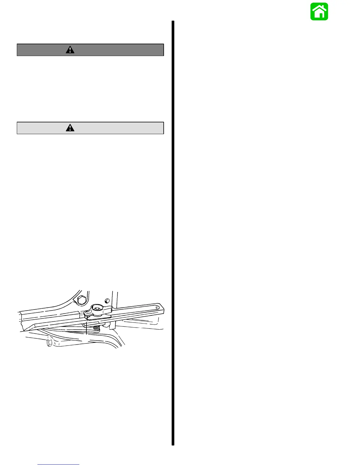
5. Insert trim tab bolt into hole in rear of gear
housing to driveshaft housing machined surface.
6. Shift gear housing into forward gear and place
guide block anchor pin into forward gear position.
51900
a
a - Guide Block Anchor Pin
7. Position gear housing so that the driveshaft is
protruding into driveshaft housing.
NOTE: If, while performing Step 8, the driveshaft
splines will not align with crankshaft splines, place a
propeller onto propeller shaft and turn it
counterclockwise as the gear housing is being
pushed toward driveshaft housing.
8. Move gear housing up toward driveshaft
housing, while aligning shift shaft splines and
water tube with water tube guide (in water pump
cover).
9. Place flat washers onto studs (located on either
side of driveshaft housing). Start a nut on these
studs and tighten finger-tight.
10. Start bolt at rear of gear housing inside trim tab
recess. DO NOT tighten bolt at this time.
11. Recheck shift shaft spline engagement and
correct if necessary.
IMPORTANT: Do not force gearcase up into place
with attaching nuts.
12. Evenly tighten 2 nuts which were started in Step
9. Torque to listing in “Torque Specifications,”
preceding.
13. After 2 nuts (located on either side of driveshaft
housing) are tightened, check shift operation as
follows:
a. Place guide block anchor pin into forward
gear position. Rotate flywheel clockwise
(viewed from top); propeller shaft should
rotate clockwise.
b. Place guide block anchor pin into neutral
position. Propeller shaft should rotate freely
clockwise/counterclockwise.
c. Place guide block anchor pin into reverse
gear position. Rotate flywheel clockwise
(viewed from top); propeller shaft should
rotate counterclockwise.
IMPORTANT: lf shifting operation is not as
described, preceding, the gear housing must be
removed and the cause corrected.
14. Install washers and nuts onto studs (located on
bottom center of anti-cavitation plate). Torque to
listing in “Torque Specifications,” preceding.
15. Install special flat washer and nut on stud at
leading edge of driveshaft housing. Torque to
listing in “Torque Specifications,” preceding.
16. Torque bolt (started in Step 10) to listing in
“Torque Specifications,” preceding.
17. Install trim tab, adjust to position in which it had
previously been installed, and tighten securely.
18. Install plastic cap into trim tab bolt opening at rear
edge of driveshaft housing.

 Loading...