Home
Mariner Mercury
Engine
135 JET
Mariner Mercury 135 JET User Manual
4
of 1
of 1 rating
797 pages
Give review
Manual
Specs
To Next Page
To Next Page
To Previous Page
To Previous Page
Loading...
1
2
3
4
5
6
7
8
10
11
12
13
14
15
16
17
18
19
9
20
21
22
24
25
26
27
23
24
25
3B-2 - FUEL
SYSTEMS
90-824052R3 JUNE 2002
WMH 1,2,3,4,5,6,7,8,9,10,1
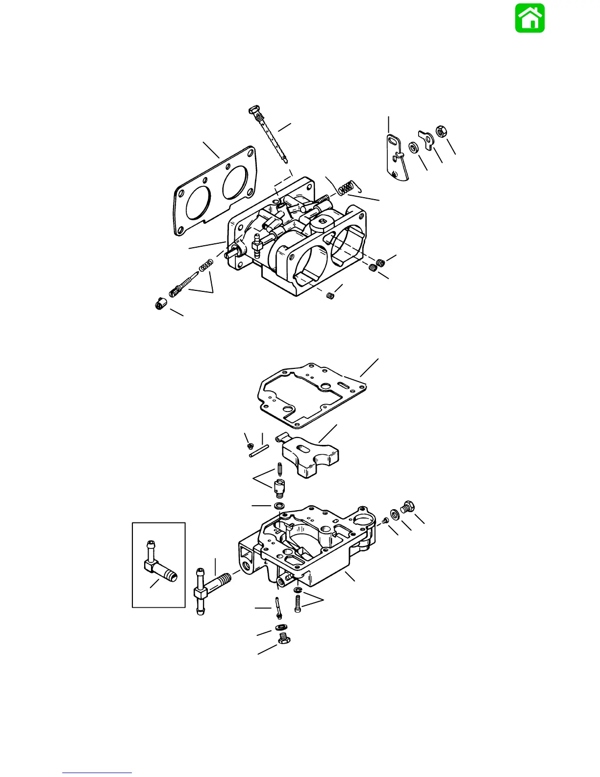
1 Carburetor Assembly
161
163
Table of Contents
Important 1 B
15
Page Numbering
3
Important Information
5
Table of Contents
15
Specifications
16
Gear Case Lubricant Capacity
16
Special Tools
16
Quicksilver Lubricant/Sealant
16
Inspection and Maintenance Schedule
16
Before each Use
16
After each Use
16
Lubrication Points
17
Checking Power Trim Fluid
19
Gear Case Lubrication
20
Gear Case Lubricant Capacity
20
Draining Gear Case
20
Checking Lubricant Level and Refilling Gear Case
20
Propeller Replacement
21
Removal
21
Installation
21
Corrosion Control Anode
22
Flushing Engine
23
Flushing Cooling System with Engine NOT Running (Using Cowl Flush Plug)
23
Flushing Cooling System with Engine Running (Using Flushing Attachment 44357A2)
23
Storage
24
Protecting External Outboard Components
24
Protecting Internal Engine Components
24
Gear Case
24
Positioning Outboard for Storage
24
Battery Storage
24
Important 1 C
26
Conditions Affecting Performance
27
Weather
27
Boat
28
Engine
29
Serial Number Location
27
Following Complete Submersion
30
Salt Water Submersion
30
Submerged While Running
30
Submerged Engine (Fresh Water)
30
Painting Procedures
31
Cleaning & Painting Aluminum Propellers & Gear Housings
31
Propeller Selection
31
Decal Application
32
Decal Removal
32
Instructions for "Wet" Application
32
Important 1 D
35
Boat Horsepower Capacity
36
Notice to Installer and Owner
36
Outboard Remote Control
36
Selecting Accessories for the Outboard
36
Selecting Steering Cables and Remote Control Cables
36
Determining Recommended Outboard Mounting Height
37
Locating Centerline of Boat Transom
38
Drilling Outboard Mounting Holes
38
Applying Counter Rotation Decals
38
Installing Outboard to Boat Transom
39
Lifting Outboard
39
Single Steering Cable and Steering Link Rod Installation
40
Installing Ride Guide Cable to Outboard Tilt Tube
40
Steering Link Rod Installation
40
Remote Control Installation
41
Counter (Left Hand) Rotation Outboards
41
Routing Location for Wiring and Hoses Thru Clamp in Bottom Cowl
41
Required Side Mount Remote Control or Ignition Key Switch Assembly
42
Boats Equipped with Side Mount Remote Control
42
Boats Equipped with Panel or Console Mount Remote Control
42
Shift and Throttle Cable Installation to the Outboard
42
Shift Cable Installation
42
Throttle Cable Installation
43
Battery Connections
44
Remote Wiring Connections
44
Fuel Connections
45
Connecting Fuel Hose to Engine
45
Portable Fuel Tank
45
Permanent Fuel Tank
45
Fuel Line
45
Set up Instructions for Oil Injection System 1D-10
45
Installing Remote Oil Tank
45
Installing Oil Hoses to Engine
46
Filling the Oil Injection System
46
Bleeding Air from Oil Injection Pump and Oil Injection Outlet Hose
47
Adjusting Oil Injection Pump
47
Propeller Installation
47
Propeller Selection
47
Power Trim System
48
General Information
48
Power Trim Operation
48
Trim "IN" Angle Adjustment
49
Checking Trim System Fluid Level
49
Trim Tab Adjustment
49
Electrical 2
51
40 Ampere Stator
52
DVA Specifications
52
Ignition Coil
52
Ignition Specifications
52
Trigger
52
Special Tools
53
Flywheel/Starter Motor
55
Ignition Coil/Voltage Regulator
57
Wiring Harness/Starter Solenoid
59
Theory of Operation
61
Description
61
Ignition Test Procedures
62
Checking for Loss of Spark
62
Direct Voltage Adaptor (DVA)
62
Troubleshooting Tips
63
Ignition Troubleshooting
64
Multimeter/Dva Tester 91-99750A1
64
Test Sequence
64
Stator High Speed Test
65
Stator Low Speed Test
65
Bias Circuit Test
66
Ignition System Test Chart
67
40 Amp Charging System
67
Ignition System
67
Stator Assembly
67
Stator Test
67
40 Ampere Stator
67
Trigger Assembly Test
68
Ignition Coil Test
68
Mercury (Tilt) Stop Switch Test
68
Ignition (Key) Switch Test
69
Ignition Switch (Soldered Connections) 2A-18
69
Ignition Switch (Bullet Connections)
70
Low Speed/High Speed Spark Advance Module Description
70
Tests for Proper Function of Low Speed
70
Low Speed Spark Advance Test
70
High Speed Spark Advance Test
70
Low Speed/High Speed Spark Advance Module Removal
71
Low Speed/High Speed Spark Advance Module Installation
71
Idle Stabilizer Modules
71
Idle Stabilizer Description
71
Test for Proper Function of Idle
71
Stabilizer
71
Idle Stabilizer Shift System Description
71
Test for Proper Function of Idle Stabilizer Shift System
72
Troubleshooting Idle Stabilizer Shift System
72
Idle Stabilizer Module Removal
72
Idle Stabilizer Module Installation
72
Ignition Components Removal and Installation
73
Flywheel Removal and Installation
73
Stator Assembly Removal and Installation
74
Trigger Plate Assembly Removal and Installation
75
Ignition Coil Removal and Installation 2A-25
76
Switch Box(Es) Removal and Installation
77
Spark Plug Wire Routing (Production Outboards)
78
Spark Plug Wire Routing (High Performance Outboards)
79
Electrical 2
81
Battery Cable Size
82
Special Tools
82
Specifications
82
Battery
83
Precautions
83
Specific Gravity Readings
83
Specific Gravity Cell Comparison Test
84
Charging a Discharged Battery
84
Electrolyte Level
84
Battery Charging System Description
85
Winter Storage of Batteries
85
Battery Charging System Troubleshooting
86
General Troubleshooting
86
40 Ampere Alternator System
86
Amp Stator Test (Alternator Coils Only)
86
Troubleshooting 40 Amp Alternator System
86
Determining Cause of Problem
87
Problem: Constant High Output
87
Problem: no Output
87
Regulation Voltage Check
87
Voltage Regulator Test
88
Removal of Voltage Regulators
88
Installation of Voltage Regulator/Rectifier
89
Incorporating a Battery Isolator with
90
V-6 40 Amp Charging System
90
System Wired for Split Output
90
20 Amperes to Auxiliary Battery
90
20 Amperes to Cranking Battery
90
System Wired for 40 Ampere Output to Isolator
91
Starter System
92
Starter System Components
92
Description
92
Troubleshooting the Starter Circuit
92
Starter Circuit Troubleshooting Flow Chart
93
Starter Removal and Installation
94
Removal
94
Installation
95
Disassembly
95
Starter Cleaning, Inspection and Testing
96
Cleaning and Inspection
96
Testing
96
Starter Reassembly
98
Starter Solenoid Test
100
Electrical 2
102
Timing/Synchronizing/Adjusting
103
Specifications
103
Carbureted Models
103
Electronic Fuel Injection Models
104
Special Tools
104
Adjustments
105
Carburetor Models
105
Carburetor Synchronization
105
Timing Pointer Adjustment
105
Carburetor/Oil Pump Synchronization
106
Maximum Timing Adjustment
107
Timing Adjustments
107
Idle Speed Adjustment
108
Primary Pickup Timing Adjustment
108
Adjustments
109
Electronic Fuel Injection Models
109
Timing Pointer Adjustment
109
Throttle Cam Adjustment
110
Static Idle Timing Adjustment (Cranking Engine with Starter)
111
Maximum Throttle
112
Maximum Timing Adjustment for 225 Pro Max/Super Magnum
112
Static Maximum Timing Adjustment (Cranking Engine with Starter)
112
Throttle Position Sensor (TPS) Adjustment
113
Idle Adjustment
114
Idle Timing (Engine Running)
114
Throttle Cable Installation
115
Throttle Valve/Oil Pump Synchronization
115
Detonation Control (200 Model)
116
Maximum Timing Adjustment (Engine Running)
116
Electrical 2
118
Wiring Diagram 135/150
119
Wiring Diagram XR6/MAG III/175
120
Wiring Diagram 200
121
Wiring Diagram 200 Carb Serial # 0D077248 Thru Serial # 0D122746
122
Wiring Diagram 150/175 EFI
123
Wiring Diagram 200 EFI
124
Wiring Diagram 200 Pro Max/Super Magnum (Early Model with Detonation Module)
125
Wiring Diagram 150/200/225 Pro Max/Super Magnum
126
Wiring Diagram105/140 Jet
127
Power Trim Wiring Diagram with Relays
129
Instrument Wiring Connections
130
Commander 3000 Classic Panel Remote Control
131
Commander 3000 Panel Remote Control
132
Commander Side Mount Remote Control (Power Trim/Tilt Electric Start with Warning Horn) Wiring Diagram
136
Commander 2000 Side Mount Remote Control (Power Trim/Tilt Electric Start with Warning Horn) Wiring Diagram
137
Oil Level Gauge Wiring Diagram
138
Visual Warning Wiring Diagram
139
Instrument/Lanyard Stop Switch Wiring Diagram
140
Instrument/Lanyard Stop Switch Wiring Diagram (Dual Outboard)
140
QSI Gauge Wiring Diagrams
143
Tachometer Wiring Diagram
143
Water Temperature Gauge
143
Oil Level Gauge Wiring
144
Engine Synchronizer Wiring Diagram
145
Maintenance
145
Multi-Function Gauge
146
Panel Mount Remote Control Wiring Installation
147
Side Mount Remote Control Wiring Installation
148
Fuel Systems
149
Fuel Systems
150
Special Tools
151
Specifications
151
Fuel Pump Pressure @ W.O.T
151
Fuel Pump Pressure @ Idle
151
Fuel Pump
152
General Information
154
Checking for Restricted Fuel Flow Caused by Anti-Siphon Valves
154
Fuel Pump Description/Operation
154
Testing Fuel Pump
155
Checking Fuel Pump Lift (Vacuum)
155
Vacuum Test Troubleshooting
156
Fuel Pump Removal/Disassembly
156
Cleaning/Inspection
157
Reassembly/Lnstallation
157
Assembly
157
Fuel Systems
160
Notes
161
WMH 1,2,3,4,5,6,7,8,9,10,11 Carburetor Assembly
162
WMH 1,2,3,4,5,6,7,8,9,10,11 Carburetor Specifications
164
WMH 12,13,14,15,16,27 Carburetor Assembly
166
WMH 12,13,14,15,16,27 Carburetor Specifications
168
WMH 21,22,23,25,26,28 Carburetor Assembly
170
WMH 21,22,23,25,26,28 Carburetor Specifications
172
WMH 30,31,32,33,34,39 Carburetor Assembly
174
WMH 30,31,32,33,34,39 Carburetor Specifications
176
Wmv 1/1A, 2/2A, 3/3A, 4/4A, 5/5A
178
WMV 1,2,3,4,5 Carburetor Front View
182
WMV 1,2,3,4,5 Carburetor Specifications
182
Fuel System - Troubleshooting
183
General Information
183
Reed Valve Leak Test
185
Tools Needed for Test
185
Thermal Air Valve Circuit Description
186
WMH Carburetor Fuel Circuit Description
186
Idle Circuit Description
186
Idle Circuit Adjustments
186
Off-Ldle Circuit Description
187
Back Draft Circuit Description
187
High Speed Fuel Circuit Description
187
High Speed Fuel Circuit Adjustments
187
Carburetor Placement
188
Jet Location for each Cylinder
188
WMV Carburetor Fuel Circuit Description
189
Float Bowl Circuit
189
Idle Circuit
189
Cold Start Circuit
190
Off-Idle Circuit
190
Main Circuit
191
Back Draft Circuit
191
Carburetor Placement and Jet Location for each Cylinder (WMV Carburetors)
192
High Altitude Recommendations
193
High Altitude Jet Chart
194
Enrichener System Description
195
Enrichener Valve Replacement
196
Enrichener Valve Test
196
Carburetor Disassembly
197
Carburetor Jet Removal
197
Fuel Bowl Removal and Disassembly
199
Throttle Shaft Component Removal
200
Carburetor Cleaning and Inspection
200
Carburetor Reassembly
200
Throttle Shaft Component Installation
200
Fuel Bowl Reassembly
201
Carburetor Jet Installation
202
Installing Carburetor(S) to Engine
203
Removing Carburetor(S) from Engine
197
Fuel Line and Primer Bulb Assembly
204
Fuel Line Clamp Removal and Installation
205
Fuel Systems
207
Special Tools
208
Specifications
208
Electronic Control Module (ECM) Assembly
209
Fuel Management System
211
Fuel Pump and Fuel Filter
215
Electronic Fuel Injection (Efl) System
217
Introduction
217
Using the Test Procedures
217
EFI System Tests
218
Safety Precautions
218
Fuel Injection System Function
218
Outboard Powerhead View
217
Preliminary Steps
219
Ignition Spark Check
219
Electronic Fuel Injection Set up
219
Fresh Quality Fuel
220
Low Battery Voltage
220
Fuel Flow Diagram
221
Fuel Flow Components
222
EFI Electrical Diagram
223
EFI Electrical Components
224
EFI Fuel Management (Low Pressure Fuel Route)
226
EFI Fuel Management (High Pressure Fuel Route)
227
Fuel Rail Electrical/Fuel Determination
228
EFI System Test Procedures
229
Fuel Gauge Connection/Pressure Test
229
Vapor Separator Fuel Delivery Test
230
Vapor Separator Float Test
230
Water Separating Filter Flow Test
231
Pulse Fuel Pump Delivery Test
232
Final Filter Check and De-Pressurizing EFI System Procedures
233
Pressure Regulator Test
234
Electric Fuel Pump Test
235
Voltage Test Chart
237
Injector Electrical Harness Test
238
Injector Fuel Delivery Test
238
Injector Operation Test
239
Induction Manifold Leak Check
240
Air Temperature Sensor Test
241
Engine Head Temperature Sensor Test
242
Detonation Control System Test (200 Models Only)
242
Detonation Sensor Check
243
Detonation Control Module Check
243
Throttle Position Sensor Test
244
Map Sensor Test
244
Problem Diagnosis
244
EFI Induction Manifold Removal
247
Water Separating Filter Assembly Removal
248
Throttle Position Sensor/Temperature Sensor
248
Fuel Injector Harness Disconnections
248
Oil Reservoir Removal
249
Final Filter Assembly Removal
249
Electric Fuel Pump Removal
250
Vapor Separator Removal
250
Vapor Separator Disassembly
251
Pressure Regulator Removal and Disassembly
251
Vapor Separator Float Removal
251
Vapor Separator Float Installation
253
Manifold Removal
254
EFI Induction Manifold Disassembly
255
Air Temperature Sensor Removal
255
Throttle Position Sensor Removal
256
Fuel Rail Removal
256
Fuel Rail Disassembly
257
Fuel Injector Removal and Disassembly
258
Injector Harness Removal
259
Throttle Linkage Removed
259
EFI System Cleaning and Inspection
260
Cleaning
260
Inspection
260
Induction Manifold Assembly
261
Injector Harness Installation
261
Fuel Injector Assembly and Installation
262
Fuel Rail Assembly
262
Fuel Rail Installation
263
Throttle Position Sensor Installation
264
Air Temperature Sensor Installation
264
EFI Induction Manifold Installation
265
Vapor Separator Installation
267
Electric Fuel Pump Installation
267
Final Filter Assembly Installation
268
Oil Reservoir Installation
269
Throttle Position Sensor and Temperature Sensor Fuel Injector Harness Connections
269
Water Separating Filter Assembly Installation
270
ECM Installation
270
Engine Head Temperature Sensor Installation
271
Fuel Systems
273
Special Tools
274
Specifications
274
Detonation Controller/Air Temperature Sensor/Throttle Position Sensor
276
Electronic Control Module (ECM) Assembly
277
Fuel Management System
279
Fuel Pump
283
Electronic Fuel Injection (Efl) System
285
Introduction
285
Using the Test Procedures
285
EFI System Tests
286
Safety Precautions
286
Fuel Injection System Function
286
Outboard Powerhead View
285
Preliminary Checks
287
Fuel Flow Diagram
289
Fuel Flow Component Description
290
Fuel Injectors
290
EFI Electrical Components (from Electrical Component Diagram)
294
EFI Fuel Management (Low Pressure Fuel Route)
296
EFI Fuel Management (High Pressure Fuel Route)
297
Fuel Rail Electrical/Fuel Determination
298
EFI System Test Procedures
299
Fuel Gauge Connection/Pressure Test
299
Vapor Separator Fuel Delivery Test
300
Vapor Separator Float Test
301
Water Separating Filter Flow Test
301
Pulse Fuel Pump Delivery Test
302
Final Filter Check and De-Pressurizing EFI System Procedures
302
Pressure Regulator Test
304
Electric Fuel Pump Voltage Test
305
Voltage Test Chart
306
Injector Electrical Harness Test
307
ECM Injector Driver Test
307
Injector Fuel Delivery Test
307
Injector Operation Test
308
Induction Manifold Leak Check
309
Air Temperature Sensor Test
310
Engine Head Temperature Sensor Test
310
Detonation Control System Test (200 Models Only)
311
Detonation Sensor Check
311
Detonation Control Module Check
312
Throttle Position Sensor Test
312
Map Sensor Test
313
Problem Diagnosis
314
EFI Induction Manifold Removal
317
Water Separating Filter Assembly Removal
318
Water Separating Filter Assembly Installation
319
Throttle Position Sensor and Temperature Sensor Fuel Injector Harness Disconnections
319
Oil Reservoir Removal
320
Fuel Pressure Regulator Removal
320
Fuel Pressure Regulator Disassembly
321
Fuel Pressure Regulator Reassembly
321
Vapor Separator Removal
321
Vapor Separator Disassembly
322
Vapor Separator Reassembly
324
Installing Vapor Separator Assembly to Induction Manifold
326
Manifold Removal
327
EFI Induction Manifold Disassembly
328
Air Temperature Sensor Removal
328
Throttle Position Sensor Removal
329
Fuel Rail Removal
329
Fuel Rail Disassembly
330
Fuel Injector Removal and Disassembly
331
Injector Harness Removal
332
Throttle Linkage Removed
332
EFI System Cleaning and Inspection
333
Cleaning
333
Inspection
333
Induction Manifold Assembly
334
Injector Harness Installation
334
Fuel Injector Assembly and Installation
335
Fuel Rail Assembly
335
Fuel Rail Installation
336
Throttle Position Sensor Installation
337
Air Temperature Sensor Installation
337
EFI Induction Manifold Installation
338
Oil Reservoir Installation
339
Vapor Separator Installation
340
Throttle Position Sensor, Air Temperature Sensor and Fuel Injector Harness Connections
341
ECM Installation
342
Engine Head Temperature Sensor Installation
343
Fuel Systems
345
Operation of the Oil Injection System
346
Oil Injection Components
347
Oil Injection Flow System
348
Pump Drive Assembly
349
Pump Drive System
349
Set up Instructions for Oil Injection System
350
Oil Injection Pump
353
Oil Pump Removal
353
Worm Bushing
354
Worm Bushing Removal
354
Worm Bushing Installation
354
Oil Injection Pump Installation
354
Installing Drive Gear (for Oil Injection Pump) Onto Crankshaft
355
Motion Sensor
355
Oil Injection System Troubleshooting Chart
356
Oil Pump Volume (Flow) Test
360
Oil Warning Module
360
Engine Mounted Oil Reservoir
360
Emission Control Information
362
Table of Contents
363
Exhaust Emissions Standards
364
What Are Emissions
364
Hydrocarbons - HC
364
Carbon Monoxide - CO
364
Oxides of Nitrogen - Nox
364
Controlling Emissions
364
Stoichiometric (14.7:1) Air/Fuel Ratio
364
Outboard Hydrocarbon Emissions Reductions
365
Stratified Vs Homogenized Charge
366
Homogenized Charge
366
Stratified Charge
366
Emissions Information
367
Manufacturer's Responsibility
367
Dealer Responsibility
367
Owner Responsibility
367
EPA Emission Regulations
367
Service Replacement Certification Label
368
Decal Location for 1998 Models
369
Powerhead
371
Powerhead Specifications
372
Special Tools
373
Powerhead Repair Stand
374
Cylinder Block and End Caps
375
Exhaust Manifold and Exhaust Plate
377
Reed Block and Cylinder Head
379
Crankshaft, Pistons and Connecting Rods
381
Torque Sequence
383
General Information
384
Powerhead Removal from Driveshaft Housing
384
Removing Engine Components
388
Powerhead Disassembly
389
Water Pressure Relief Valve Components
395
Torque Specifications
395
Cleaning and Inspection
396
Cylinder Block and Crankcase Cover
396
Special Service Information
396
Cylinder Bores
396
Honing Procedure
396
Pistons and Piston Rings
398
Cleaning Piston Ring Grooves
398
Measuring Piston Roundness
399
Cylinder Heads and Exhaust Divider Plate
399
Crankshaft
400
Crankshaft (and End Cap) Bearings
400
Reed Block Assembly
401
Reed Block Housing
401
Connecting Rods
401
Powerhead Reassembly and Installation
404
General
404
Crankshaft Installation
407
Special Information
407
Piston and Connecting Rod Reassembly
408
Piston and Piston Ring Combinations
410
Piston Installation (Standard and High Performance Models)
411
Crankcase Cover Installation (Standard and High Performance Models)
413
Assembly of Reed Blocks to Intake Manifold (Standard and High Performance Models)
414
Assembly of Exhaust Divider Plate to Block (Standard and High Performance Models)
414
Cylinder Head Installation (Standard and High Performance Models)
415
Bleed Line Routing (Carbureted Models)
416
Front View
416
Port Side View
416
Starboard Side View
416
Bleed Line Routing (Fuel Injected Models)
416
Port Side View
417
Starboard Side View
417
Reinstalling Engine Components
417
Notes
418
Throttle Lever and Shift Shaft
419
Powerhead Installation on Driveshaft Housing
423
Break-Ln Procedure
428
Break-In Fuel Mixture
428
Engine Break-In Procedure (All Models)
428
Gasoline/Oil Mixing Ratio Chart
428
Powerhead
430
Special Tools
431
Specifications
431
Thermostat
431
Water Pressure
431
Water Flow
433
Description
433
Troubleshooting
437
Thermostat Test
437
Water Pressure Check
438
Water Pump Cleaning and Inspection
439
Problem Diagnosis
440
MID-Section
442
Notes
443
Swivel Bracket and Steering Arm
444
Transom Brackets (S/N-0G590000
446
Drive Shaft Housing and Exhaust Tube
450
Drive Shaft Housing and Dyna-Float Suspension
452
Removal and Disassembly
452
Shift Linkage Assembly
452
Reassembly and Installation
454
MID-Section
458
Power Trim Specifications
459
Special Tools
459
Power Trim Components
460
Power Trim Motor
462
Power Trim - General Information
463
Description
463
Trimming Characteristics
463
Trailering Outboard
463
Tilting Outboard Manually
464
Trim "In" Angle Adjustment
464
Striker Plate Replacement
464
Anode Plate
465
Trim Indicator Gauge
465
Check, Fill and Purge - Power Trim System
465
Troubleshooting
466
Power Trim System with Relays and 2 Wire Trim Motor
468
Electrical System Troubleshooting
469
General Checks
469
Troubleshooting the "Down Circuit
469
Troubleshooting the "Up" Circuit
470
Troubleshooting the "Down" and "Up" Circuits (All Circuits Inoperative)
471
Power Trim Assembly Removal and Installation
472
Removal
472
Installation
474
Testing Power Trim System with Test Gauge Kit (91-52915A6)
475
UP" Pressure Check
475
DOWN" Pressure Check
477
Hydraulic Repair
479
Trim Rod End Cap Seal
480
Tilt Ram
480
Disassembly
481
Scraper Seal Replacement
483
Motor and Electrical Tests/Repair
485
Trim Pump Motor Test
485
Motor Disassembly
486
Armature Tests
486
Motor Repair
487
Reassembly
490
Reassembly - Motor and Pump
491
Priming Power Trim System
492
Trim Sender Test
493
Trim Indicator Wiring Diagrams
494
Lower Unit
495
Lower Unit
496
Forward Gear Backlash
497
Lubricant Capacity
497
Pinion Depth
497
Reverse Gear Backlash
497
(S/N-0G437999 & Below)
504
Gear Housing (Prop Shaft)(Standard Rotation) (S/N-0G437999 & BELOW)
504
Gear Housing (Drive Shaft) (CLE) (Standard Rotation) (Pro Max/Super Magnum Models)
506
Gear Housing (Prop Shaft) (CLE) (Standard Rotation) (Pro Max/Super Magnum Models)
508
Gear Housing (Drive Shaft) (Standard Rotation) (Torque Master)(Pro Max/Super Magnum Models)
510
Gear Housing (Prop Shaft) (Standard Rotation) (Torque Master) (Pro Max/Super Magnum Models)
512
Gear Housing (Driveshaft) (Standard Rotation) (Sportmaster)
514
Gear Housing (Prop Shaft) (Standard Rotation) (Sportmaster)
518
General Service Recommendations
520
Removal, Disassembly, Cleaning and Inspection - Standard Rotation
521
Removal
521
Draining and Inspecting Gear Housing Lubricant
522
Water Pump
523
Cleaning and Inspection
523
Removal and Disassembly
523
Bearing Carrier and Propeller Shaft Removal
524
Shift Shaft
526
Cleaning and Inspection
526
Disassembly
526
Disassembly- Bearing Carrier
527
Propeller Shaft
528
Inspection
528
Disassembly (Std. Gear Cases)
530
Pinion Gear and Drive Shaft
531
Removal
531
Forward Gear
533
Removal and Disassembly
533
Gear Housing
534
Bearing Carrier
535
Reassembly
535
Driveshaft Needle Bearing
535
Reassembly/Installation
535
Reassembly and Installation Standard Rotation
535
Forward Gear
537
Reassembly
537
Forward Gear Bearing Race
537
Installation
537
Driveshaft and Pinion Gear
538
Reassembly/Installation
538
Play (Sport Master)
543
Drive Shaft End Play
543
Clutch Actuator Rod
545
(Std. Gear Case)
545
Reassembly/Shimming (High-Performance Gear Cases)
546
Propeller Shaft
546
Shift Shaft Bushing
546
Reassembly
546
Water Pump
549
Gear Lubricant Filling Instructions
551
Installing Gear Housing to Drive Shaft Housing
552
Propeller Installation
553
Lower Unit
556
Gear Housing (Prop Shaft)(Counter Rotation) (S/N-0G437999 & BELOW)
564
Gear Housing (Driveshaft)(Counter Rotation) (Sportmaster)
568
Gear Housing (Prop Shaft)(Counter Rotation) (Sportmaster)
572
General Service Recommendations
576
Removal, Disassembly, Cleaning and Inspection of Counter Rotation (Left Hand) Gear Housing
577
Removal
577
Draining and Inspecting Gear Housing Lubricant
578
Water Pump
579
Cleaning and Inspection
579
Removal and Disassembly
579
Bearing Carrier and Propeller Shaft Removal
580
Shift Shaft
583
Cleaning and Inspection
583
Disassembly
583
Disassembly- Bearing Carrier
583
Propeller Shaft
584
Disassembly
584
Inspection
584
Clutch Actuator Rod
586
Cleaning and Inspection
586
Disassembly
586
Forward Gear and Bearing Adapter
587
Disassembly/Cleaning/Inspection
587
Pinion Gear and Driveshaft
588
Removal
588
Reverse Gear
591
Cleaning and Inspection
591
Removal and Disassembly
591
Gear Housing
592
Cleaning and Inspection
592
Driveshaft Needle Bearing
592
Reassembly/Installation
592
Reassembly and Installation of Counter Rotation Gear Housing
592
Bearing Carrier, Forward Gear and Bearing Adaptor
593
Reassembly
593
Propeller Shaft Needle Roller Bearing and Oil Seal Installation
593
Reverse Gear and Bearing Cup Adaptor Reassembly
594
Driveshaft and Pinion Gear
595
Reassembly/Installation
595
Pinion Gear Depth
597
Determining Pinion Gear Depth
597
Setting/Checking Driveshaft End Play (Sport Master Only)
598
Reverse Gear
600
Determining Reverse Gear Backlash
600
Forward Gear
601
Propeller Shaft/Forward Gear Bearing Adapter/Bearing Carrier
603
Reassembly
603
Clutch Actuator Rod
606
Reassembly/Shimming
606
Propeller Shaft
607
Shift Shaft Bushing
607
Reassembly
607
Water Pump
611
Gear Lubricant Filling Instructions
613
Installing Gear Housing to Driveshaft Housing
613
Propeller Installation
614
Lower Unit
617
Gear Housing Specifications (1.78:1 Ratio)
618
Special Tools
618
1.78:1 Ratio
618
Gear Housing (Prop Shaft) - Xr6/Magnum III - 1.78:1 Ratio
623
General Service Recommendations
625
Removal, Disassembly, Cleaning and Inspection
626
Removing Gear Housing from Driveshaft Housing
626
Draining Lubricant from Gear Housing
627
Water Pump
628
Removal and Disassembly
628
Cleaning and Inspection
629
Bearing Carrier and Propeller Shaft Removal
629
Bearing Carrier Cleaning and Inspection
630
Bearing Carrier Disassembly
630
Propeller Shaft Cleaning and Inspection
631
Propeller Shaft Disassembly
632
Pinion Gear and Driveshaft
632
Cleaning and Inspection
633
Forward Gear and Bearings
634
Cleaning and Inspection
634
Removal and Disassembly
634
Shift Shaft, Bushing and Cam
635
Shift Shaft Removal
635
Gear Housing
635
Cleaning and Inspection
635
Driveshaft Needle Bearing
636
Removal of Driveshaft Needle Bearing - Early Model
636
Removal of Driveshaft Needle Bearing - Late Model
637
Driveshaft Needle Bearing
637
Reassembly and Installation
637
Driveshaft Needle Bearing
638
Installation - Late Model
638
Late Model
638
Lower Shift Shaft and Bushing
639
Reassembly and Installation
639
Bearing Carrier
640
Reassembly
640
Forward Gear and Race
640
Driveshaft and Pinion Gear
642
Reassembly/Installation
642
Determining Pinion Gear Depth
643
Propeller Shaft
644
Reassembly
644
Determining Forward Gear Backlash
645
Water Pump
647
Reassembly/Installation
647
Filling Gear Housing with Lubricant
648
Installing Gear Housing to Driveshaft Housing
648
Propeller Installation
650
Lower Unit
652
Gear Housing Specifications (Standard Rotation)
653
Special Tools
653
(S/N-0G438000
658
(S/N-0G438000
660
General Service Recommendations
662
Removal, Disassembly, Cleaning and Inspection - Standard Rotation
663
Draining and Inspecting Gear Housing Lubricant
664
Cleaning and Inspection
665
Removal and Disassembly
665
Water Pump
665
Bearing Carrier and Propeller Shaft Removal
666
Cleaning and Inspection
668
Shift Shaft
668
Disassembly- Bearing Carrier
669
Balance Wheels
670
Propeller Shaft
670
Cleaning and Inspection
672
Clutch Actuator Rod
672
Pinion Gear and Driveshaft
672
Cleaning and Inspection
673
Cleaning and Inspection
674
Forward Gear
674
Removal and Disassembly
674
Cleaning and Inspection
675
Gear Housing
675
Reassembly and Installation Standard Rotation
675
Reassembly/Installation
675
Bearing Carrier
676
Forward Gear
677
Forward Gear Bearing Race
678
Driveshaft and Pinion Gear
679
Reassembly/Installation
679
Pinion Gear Depth/Forward Gear Backlash/Reverse Gear Backlash
680
Determining Pinion Gear Depth
680
Determining Forward Gear Backlash
681
Clutch Actuator Rod
683
Shift Shaft Bushing
683
Propeller Shaft
684
Water Pump
686
Gear Lubricant Filling Instructions
688
Installing Gear Housing to Driveshaft Housing
688
Propeller Installation
689
Lower Unit
692
Gear Housing (Prop Shaft) (Counter Rotation) (S/N-0G438000 & UP)
700
General Service Recommendations
704
Removal, Disassembly, Cleaning and Inspection of Counter Rotation (Left Hand) Gear Housing
705
Draining and Inspecting Gear Housing Lubricant
706
Water Pump
707
Cleaning and Inspection
707
Removal and Disassembly
707
Bearing Carrier and Propeller Shaft
708
Shift Shaft
711
Cleaning and Inspection
711
Disassembly- Bearing Carrier
711
Propeller Shaft
712
Clutch Actuator Rod
714
Cleaning and Inspection
714
Forward Gear and Bearing Adapter
714
Disassembly/Cleaning/Inspection
714
Pinion Gear and Driveshaft
715
Cleaning and Inspection
717
Reverse Gear
717
Removal and Disassembly
717
Cleaning and Inspection
718
Gear Housing
719
Cleaning and Inspection
719
Driveshaft Needle Bearing
719
Reassembly/Installation
719
Reassembly and Installation of Counter Rotation Gear Housing
719
Bearing Carrier, Forward Gear and Bearing Adaptor
720
Propeller Shaft Needle Roller Bearing and Oil Seal Installation
720
Reverse Gear and Bearing Cup Adaptor Reassembly
721
Driveshaft and Pinion Gear
723
Reassembly/Installation
723
Pinion Gear Depth
724
Determining Pinion Gear Depth
724
Forward Gear
726
Reverse Gear
726
Determining Reverse Gear Backlash
726
Propeller Shaft/Forward Gear Bearing Adapter/Bearing Carrier
729
Water Pump
735
Reassembly/Installation
735
Gear Lubricant Filling Instructions
737
Installing Gear Housing to Driveshaft Housing
737
Propeller Installation
738
Jet Outboards
741
Jet Components
745
Engine Horsepower Selection
746
Selecting a Boat that Is Best Suited for Jet Power
746
Locate Centerline of the Outboard
747
Outboard Mounting Height
747
Transom Height of the Boat
747
Water Testing
748
Checking for Cavitation
748
Shift Cable Installation Jet 105 and
749
Impeller Removal and Installation
750
Lubricating the Driveshaft Bearing
750
Flushing the Cooling System
752
Impeller Clearance Adjustment
752
Steering Pull Adjustment
752
Worn (Dull) Impeller
752
Jet Drive Removal and Installation
753
Liner Replacement
753
Bearing Carrier Disassembly
755
Bearing Carrier Reassembly
755
Installing Seals
755
Installing Upper Seals
756
Installing Driveshaft Bearing(S)
756
Installing Driveshaft
757
Installing Upper Seal Housing
758
Attachments/Control Linkage
760
Installing Production Outboards
761
Installing High Performance Outboards - Pro Max/Super Magnum Models
762
Installing Outboard on Transom
763
Lifting Outboard
764
Rideguide Steering Cable/Attaching Kit Installation (92876A1)
766
Single Cable - Single High Performance
766
Single Cable - Single Production Outboard
766
Maintenance Instructions
767
Rideguide Steering Cable/Attaching Kit Installation (92876A3)
768
Dual Cable - Single Outboard
768
Super Rideguide Steering Kit Installation
768
Steering Cable Mounting Tube Installation
769
Installing Steering Cables
769
Coupler Installation
770
Installing Link Rod
770
Steering System Tension Adjustment
771
Maintenance Instructions
772
Rideguide Steering Cable/Attaching Kit Installation (92876A6)
773
Dual Cable - Dual Outboard
773
Determine Routing of Steering Cables
773
Parallel Routed Steering Cables and Attaching Kit Installation
773
Super Rideguide Steering Kit Installation
773
Installation Requirements
773
Steering Cable Installation Starboard Outboard
774
Steering Cable Installation - Port Outboard
775
Steering Link Rod Installation
776
Steering Arm Extension Bracket Installation
777
Steering Coupler Assembly and Installation
777
Steering System Tension Adjustment (Parallel Routed Steering Cables)
779
Opposite Side Routed Steering Cables and Attaching Kit Installation
780
Steering Cable Installation - Starboard Outboard
780
Super Rideguide Steering Kit Installation
780
Steering Cable Installation - Port Outboard
781
Steering Link Rod Installation
782
Steering Arm Extension Bracket Installation
783
Steering Coupler Assembly and Installation
783
Steering System Tension Adjustment (Parallel Routed Steering Cables)
785
Trim Tab Adjustment
786
Dual Outboard - Counter Rotation Installation
786
Dual Outboard - Non Counter Rotation Installation
786
Rideguide Steering Attachment Extension Couplers
786
Maintenance Instructions
787
Transom Mounted Rideguide Attaching Kit Installation (73770A1)
788
Attaching Kit Installation
788
Steering Cable Installation
789
Maintenance Instructions
790
Clevis Attaching Kit Installation (A-70599A2)
790
Installation Instructions
790
Remote Control Installation
791
Required Side Mount Remote Control or Ignition Key Switch Assembly
791
Boats Equipped with Side Mount Remote Control
791
Boats Equipped with Panel or Console Mount Remote Control
791
Connecting Engine Wiring Harness Engine Battery Cables and Trim Wires
791
Routing Location for Wiring and Hoses Thru Clamp in Bottom Cowl
792
Remote Control Installation
793
Shift Cable Adjustment and Installation to the Engine
793
Throttle Cable Adjustment and Installation to the Engine
794
Battery Connections
795
Fuel Connections
796
Connecting Fuel Hose to Engine
796
High Performance Models - Pro Max/Super Magnum
796
Production Carburetor Models
796
Production EFI Models
796
Auxiliary Fuel Pump
797
Permanent Fuel Tank
797
Portable Fuel Tank
797
4
Based on 1 rating
Ask a question
Give review
Questions and Answers:
Need help?
Do you have a question about the Mariner Mercury 135 JET and is the answer not in the manual?
Ask a question
Mariner Mercury 135 JET Specifications
General
Brand
Mariner Mercury
Model
135 JET
Category
Engine
Language
English
Related product manuals
Mariner Mercury 175 JET
797 pages