90-824052R3 JUNE 2002 FUEL SYSTEMS - 3C-31
Injector Electrical Harness Test
Purpose: This test will determine if electrical or fuel
delivery problem exists during the fuel
delivery process by checking for open circuits
in injector harness.
Procedure: STEP 1: With outboard in water, start
and allow to warm up. Raise engine
speed to 2000-2500 RPM. Remove spark
plug leads one at a time and note RPM
change. Determine non-working (no
RPM change) cylinder. Stop engine.
STEP 2: Disconnect injector harness (4 pin
connector).
IMPORTANT: Use digital ohmmeter when testing
injector harness.
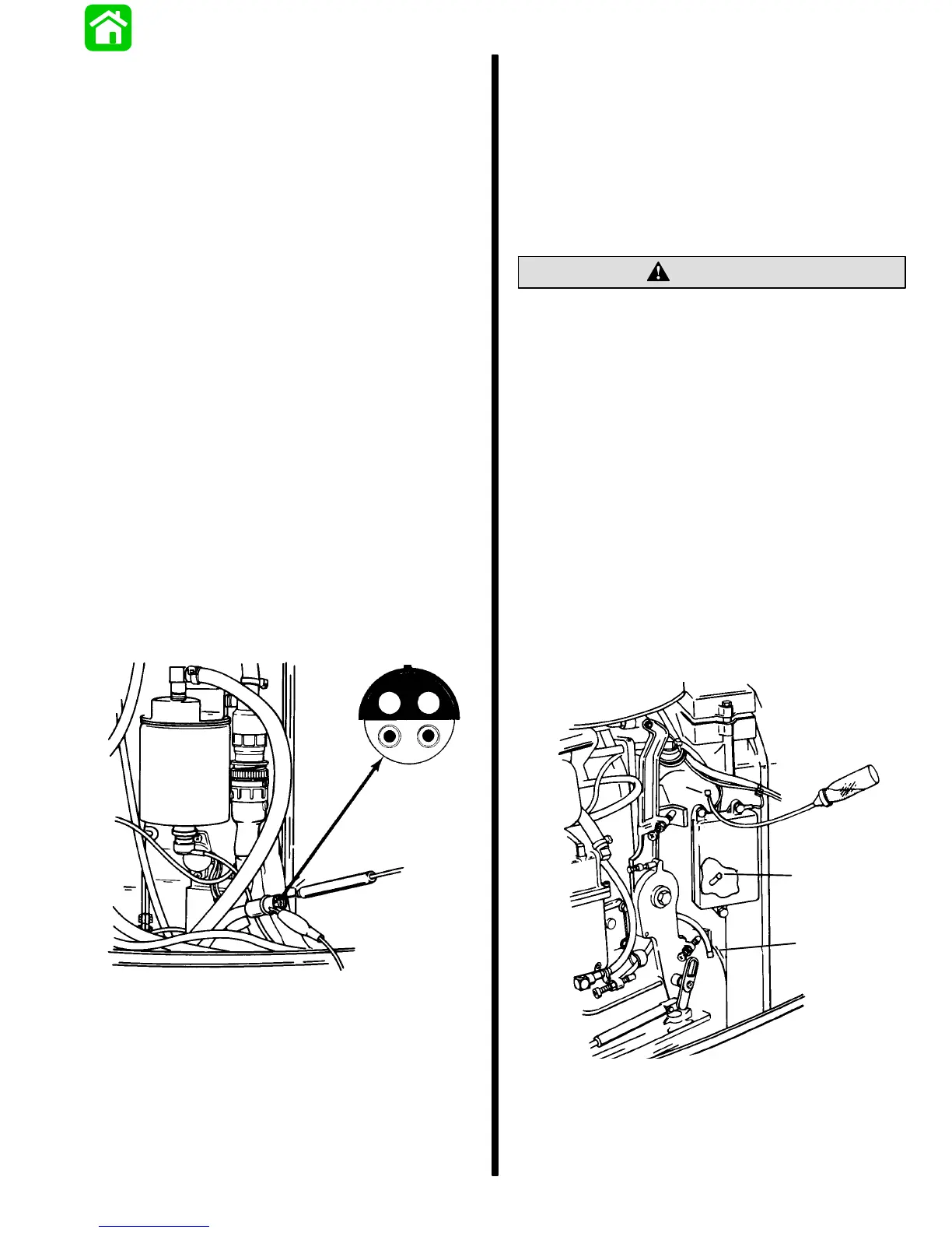
STEP 3: Connect digital ohmmeter (dial set at
200 scale) leads. Positive lead from
ohmmeter connects to positive prong “2”
(red wire) of harness connector. Connect
negative lead from ohmmeter to the
remaining wires of harness connector as
follows:
WHITE Lead = Injectors, Cylinders 1 and 2
DARK BLUE Lead = Injectors, Cylinders 3 and 4
YELLOW = Injectors, Cylinders 5 and 6
1
2
3
4
50326
(1) YELLOW
(2) RED
(3) DARK BLUE
(4) WHITE
Results: If readings are 1.1 ± .2 both injector circuits
are complete. Perform Injector Fuel Delivery
Test.
If readings are 2.2 ± .2 one injector does not have
a complete circuit. Perform induction manifold
disassembly and inspection following.
Injector Fuel Delivery Test
CAUTION
CAUTION: Switch boxes must be grounded to
engine block if removed for fuel delivery test to
prevent possible damage to ignition system.
Purpose: This test will determine if injector is deliver-
ing fuel when signal is received.
Procedure: STEP 1: Place outboard in water,
start engine and allow to warm up. Raise
engine speed to 2000-2500 RPM.
Remove spark plug leads one at a time
and note RPM change. Determine
non-working cylinder (no RPM change).
STEP 2: Using squirt bottle of fuel and hose,
inject small amount of fuel into cylinder
bleed fitting (a) on non-working cylinder.
NOTE: Switch box panel and lube alert control box
may have to be shifted to the side to allow bleed fitting
connection. Ground boxes to motor as required.
a
a
a
50342

 Loading...