90-824052R3 JUNE 2002 ELECTRICAL - 2A-21
The purpose of this system is to help prevent the
outboard from stalling when shifting into gear while
using a high pitch propeller.
IMPORTANT: On models OTHER THAN XR6 and
Magnum III on which the IDLE STABILIZER SHIFT
SYSTEM is installed as an ACCESSORY, the
maximum timing MUST BE RETARDED three
degrees. Refer to “TIMING, SYNCHRONIZING
and ADJUSTING” SECTION 2C, for proper timing
procedure.
TEST FOR PROPER FUNCTION OF IDLE
STABILIZER SHIFT SYSTEM
Connect timing light to number one spark plug lead
(top, starboard bank). Start the engine and allow it to
idle at specified engine RPM. Place outboard in gear
while monitoring ignition timing. Timing will advance
three degrees if system is functioning correctly.
TROUBLESHOOTING IDLE STABILIZER SHIFT
SYSTEM
When outboard is idling IN NEUTRAL, shift switch
circuit is in the OPEN position and system is
INACTIVE.
When outboard is shifted INTO GEAR, shift switch
circuit CLOSES. BIAS VOLTAGE from each switch
box is changed by a 6.8K (+.34K) resistor located in
the WHITE/BLACK lead between the switch boxes
and the shift switch. The shift switch is now CLOSED
and completes the circuit to ground. THREE
DEGREES of timing advance occurs when the shift
system works properly.
If the resistor is OPEN or the shift switch circuit stays
OPEN, the THREE DEGREES of advance will not
occur when the outboard is shifted into gear AND
maximum timing at W.O.T. will be RETARDED
THREE DEGREES.
If the resistor should SHORT TO GROUND, engine
timing will be overly advanced and damaging power-
head detonation will occur.
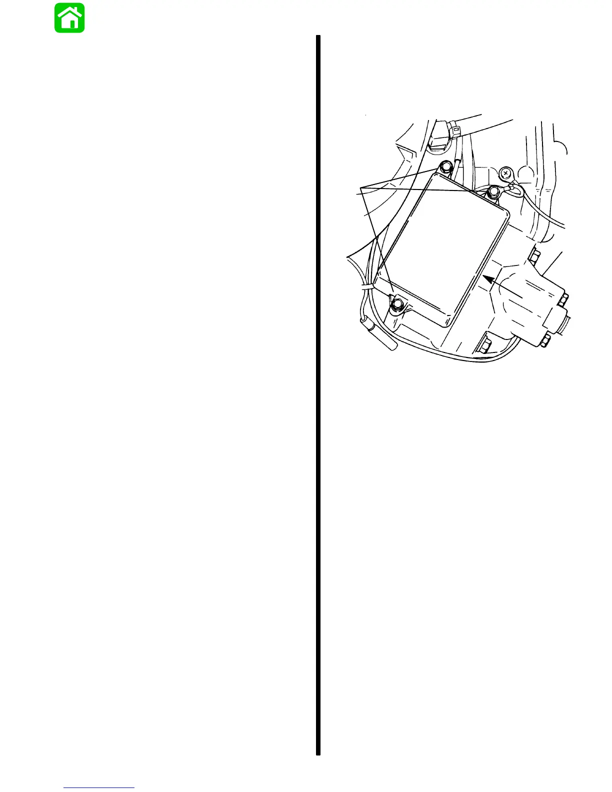
IDLE STABILIZER MODULE REMOVAL
1. Disconnect stabilizer module harness leads from
switch box.
2. Remove bolts securing idle stabilizer to power-
head.
b
a
51843
a - Idle Stabilizer
b - Bolts
IDLE STABILIZER MODULE INSTALLATION
1. Connect module harness leads to switch box
(Refer to Wiring Diagrams, Section 2D).
2. Apply Loctite 222 (FT2962-2) to threads of
module mounting bolts and secure module to
powerhead.
3. Torque bolts to 30 Ib. in. (3.5 N m).

 Loading...