90-824052R3 JUNE 2002 FUEL SYSTEMS - 3C-41
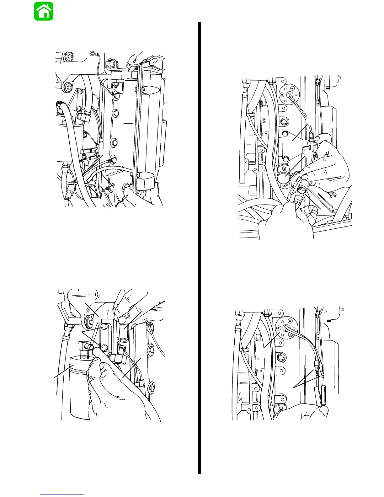
5. Carefully raise ECM (g) from studs. Disconnect
MAP sensor hose (b) at manifold fitting (i) and re-
move ECM.
g
b
i
51793
Water Separating Filter Assembly
Removal
1. Disconnect fuel inlet hose (a) and fuel delivery
hose (b) from fittings.
2. Remove screws (c), filter base (d) and spacer
block (e).
d
a
b
e
c
51793
a - Fuel Inlet Hose
b - Fuel Delivery Hose
c - Screws
d - Filter Base
e - Spacer Block
Throttle Position Sensor
Temperature Sensor Fuel Injector
Harness Disconnections
1. Disconnect throttle position sensor at 3 pin con-
nector and remove ECM harness bracket.
b
a
51787
C
a - Throttle Position Sensor
b - 3 Pin Connector
c - Bracket
2. Disconnect air temperature sensor at
connectors.
51788
b
a
a - Air Temperature Sensor
b - Connectors

 Loading...