90-824052R3 JUNE 2002 LOWER UNIT - 6A-57
Propeller Installation
WARNING
When installing or removing propeller, because
of the engine’s ease in starting, be sure that the
remote control is in neutral position and that the
key switch is “OFF.” Place a block of wood
between the anti-cavitation plate and propeller to
prevent accidental starting and to protect hands
from propeller blades while removing or
installing nut.
1. To aid in future removal of the propeller, liberally
coat the propeller shaft splines with one of the
following Quicksilver products:
– Anti-Corrosion Grease (92-78376A6)
-- Special Lubricant 101 (92-13872A1)
-- 2-4-C Marine Lubricant (92-90018A12)
-- Perfect Seal (92-34227--1)
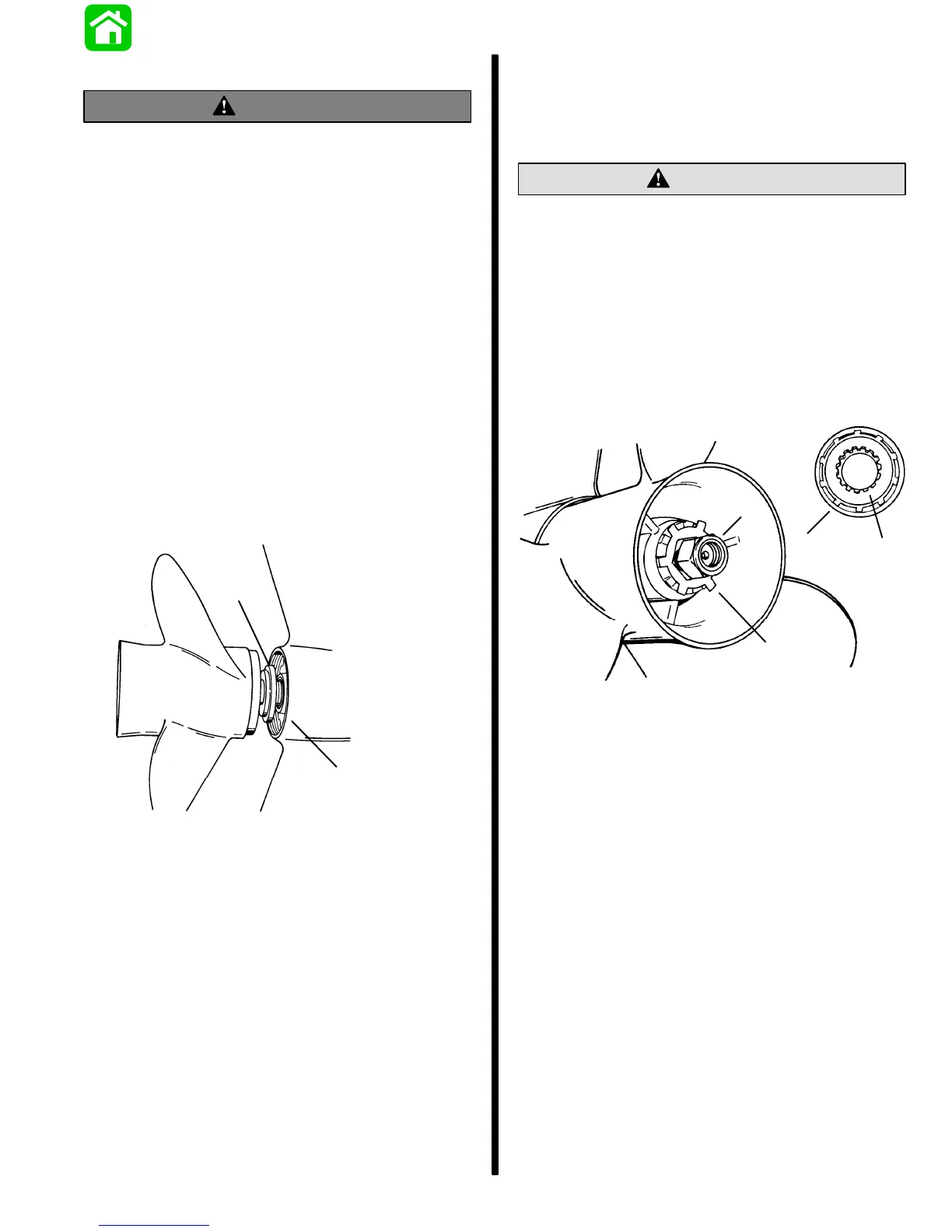
2. Place forward thrust hub over propeller shaft with
shoulder side toward propeller.
3. Place propeller on propeller shaft and slide it up
against thrust hub.
b
51866
a
a - Forward Thrust Hub
b - Propeller Shaft
4. Place continuity washer (if equipped) onto
shoulder of rear thrust hub.
5. Place rear thrust hub, tab washer and propeller
nut on propeller shaft.
6. Thread propeller nut onto propeller shaft until nut
is recessed into tab washer.
7. After propeller nut is recessed into tab washer,
tighten nut securely [minimum of 55 Ib. ft. (74.5
N·m) torque].
8. Bend 3 of the tabs of tab washer down in grooves
of rear thrust hub to secure propeller nut. (If tab
washer tabs do not align with slots, continue to
tighten propeller nut to obtain alignment. DO
NOT loosen nut to align tabs.)
CAUTION
DO NOT misinterpret propeller shaft movement
with propeller movement. If propeller and
propeller shaft together move forward-and-aft,
this is normal; how- ever, propeller should not
move forward-and-aft on propeller shaft.
9. After first use, retighten propeller nut and again
secure with tab washer (Steps 7 and 8, preced-
ing). Propeller should be checked periodically for
tightness, particularly if a stainless steel propeller
is used.
d
c
a
b
51866
a - Continuity Washer (if Equipped)
b - Rear Thrust Hub
c - Tab Washer
d - Propeller Nut

 Loading...