2A-20 - ELECTRICAL 90-824052R3 JUNE 2002
LOW SPEED/HIGH SPEED SPARK ADVANCE
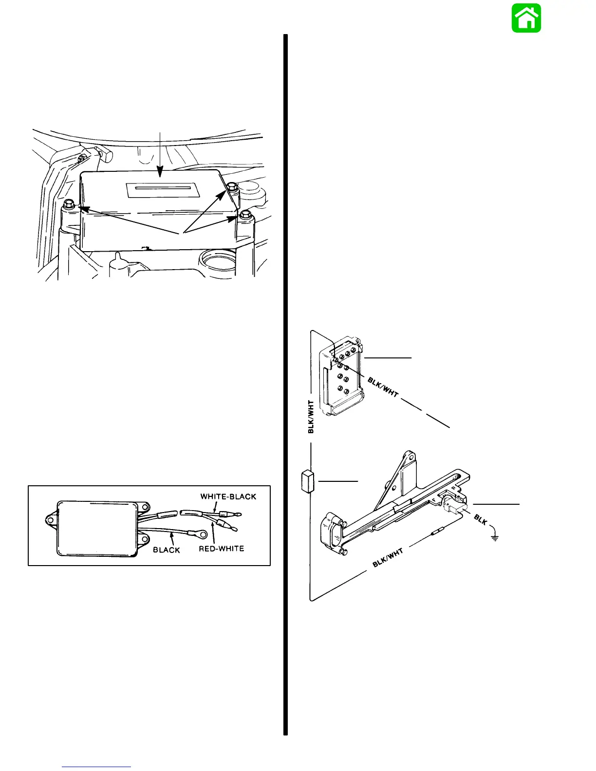
MODULE REMOVAL
1. Disconnect spark advance module harness
leads from switch box.
2. Remove 3 bolts securing module to powerhead
and remove module.
a
b
51843
a - Low Speed/High Speed Advance Module
b - Bolts (3)
LOW SPEED/HIGH SPEED SPARK ADVANCE
MODULE INSTALLATION
1. Connect module harness leads to switch box.
2. Apply Loctite 222 (FT2962-2) to threads of 3
module mounting bolts and secure module to
powerhead.
3. Torque bolts to 30 Ib. in. (3.5 N·m).
Idle Stabilizer Modules
Idle Stabilizer
IDLE STABILIZER DESCRIPTION
The idle stabilizer will electronically advance the igni-
tion timing by as much as 9° if the engine idle speed
falls below approximately 550 RPM. This timing ad-
vance raises the idle RPM to an acceptable level
(550 RPM). When the idle stabilizer senses the idle
RPM has reached the acceptable level, it returns the
timing to the normal idle timing.
TEST FOR PROPER FUNCTION OF IDLE
STABILIZER
IMPORTANT: Due to the sensitivity characteris-
tics of individual modules and tachometer vari-
ances, the engine RPM at which the module will
advance/retard the ignition timing may vary
slightly from specification.
Connect a timing light to No. 1 spark plug lead (top,
starboard bank). Start the engine, and allow it to idle
above 600 RPM, then retard the ignition timing by
slowly pulling forward on the spark advance lever.
Observe that the system is functioning by noting a
rapid spark advance (as much as 9° from the idle set-
ting) as the engine slows down to below approxi-
mately 550 RPM.
The idle stabilizer is not repairable. Should the idle
stabilizer fail to function as described, it will require
replacement.
Idle Stabilizer Shift System (XR6 and Magnum III
Models)
50707
a
b
c
d
a - Inner Switch Box
b - To Outer Switch Box
c - Resistor (6.8K)
d - Shift Switch
IDLE STABILIZER SHIFT SYSTEM
DESCRIPTION
The idle stabilizer shift system advances ignition tim-
ing three degrees each time the outboard is shifted
into gear.

 Loading...