90-824052R3 JUNE 2002 LOWER UNIT - 6B-51
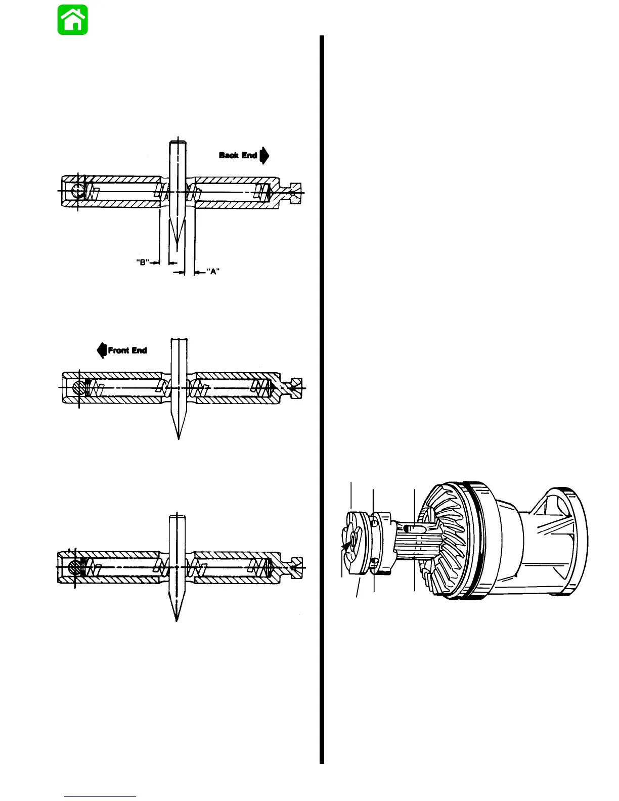
5. Measure distance (A and B) from each end of
elongated slot to the near side of cross pin tool.
The measurements taken must be equal within
1/64″ (0.4mm).
6. If measurements (taken in Step 5) are not equal
to within 1/64″, remove locating pin and re-shim
compression spring.
Clutch Actuator Rod with One Additional Shim
Washer Added to Back End
Clutch Actuator Rod with One Additional Shim
Washer Added to Front End
Clutch Actuator Rod with One Additional Shim
Washer Added to Each End
Shift Shaft Bushing
REASSEMBLY
1. Position shift shaft bushing on a press with
threaded side down.
2. Apply Loctite 271 to outside diameter of oil seal.
3. Press oil seal into shift shaft bushing with lip of
seal up.
4. Wipe any excess Loctite from oil seal and
bushing.
5. Place rubber washer against oil seal.
6. Install O-ring over threads and up against
shoulder of bushing.
7. Lubricate O-ring and oil seal with Quicksilver
2-4-C w/Teflon Marine Lubricant.
Propeller Shaft
REASSEMBLY/INSTALLATION
1. Position sliding clutch onto propeller shaft. The
“GROOVED RINGS” on the Sport Master gear
cases should be installed with the grooves
toward the front of the gear housing. On all other
gear cases, the grooves are for manufacturing
purposes only and may be positioned towards
either gear. Cross pin hole and detent holes in
sliding clutch must line up with cross pin slot and
detent notches in propeller shaft.
d
a
g
e
c
b
51913
f
a - Sliding Clutch
b - Propeller Shaft
c - Grooved Rings (Toward Front of Gear Case for Hi-Perfor-
mance Applications)
d - Cross Pin Hole
e - Detent Holes
f - Cross Pin Slot
g - Detent Notches

 Loading...