ELECTRICAL - 2B-9
90-824052R3 JUNE 2002
INCORPORATING A BATTERY ISOLATOR WITH
V-6 40 AMP CHARGING SYSTEM
A battery isolator will allow the charging system to
charge both the starting battery and an auxiliary
battery at the same time while preventing
accessories, connected to the auxiliary battery, from
drawing power from the cranking battery.
1. Install the isolator as prescribed by the
manufacturer.
IMPORTANT: After electrical connections are
made, coat all terminal connections using
Quicksilver Liquid Neoprene (92-25711) to avoid
corrosion.
2. Using BATTERY ISOLATOR HARNESS KIT
84-815366A3, charging system can be wired to
provide either 20 amps to auxiliary battery and 20
amps to cranking battery or 40 amps to isolator.
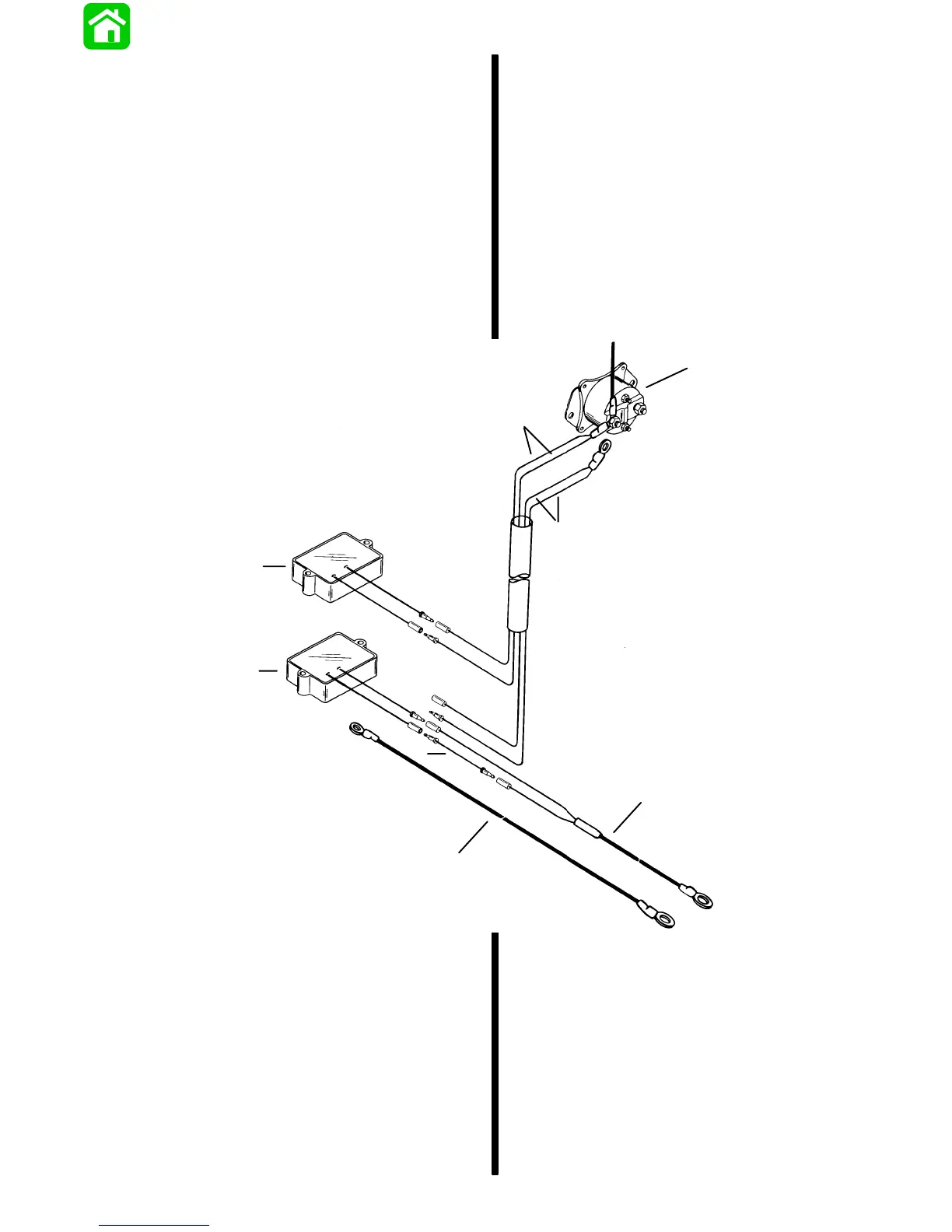
System Wired for Split Output
20 AMPERES TO AUXILIARY BATTERY;
20 AMPERES TO CRANKING BATTERY
a
b
c
d
e
f
g
h
a - Starter Solenoid
b - RED Leads – Engine Harness from Upper Regulator to
Start Solenoid
c - Disconnect (and discard) Engine Harness RED Leads to
Lower Regulator
d - Upper Regulator
e - Lower Regulator
f - Jumper Wire (from kit)
g - RED Pigtail Cable (from kit) to Auxiliary Battery “+”
Terminal
h - BLACK Cable (from kit) Route from Auxiliary Battery “–”
Terminal to suitable Engine Ground

 Loading...