3C-60 - FUEL SYSTEMS 90-824052R3 JUNE 2002
Vapor Separator Installation
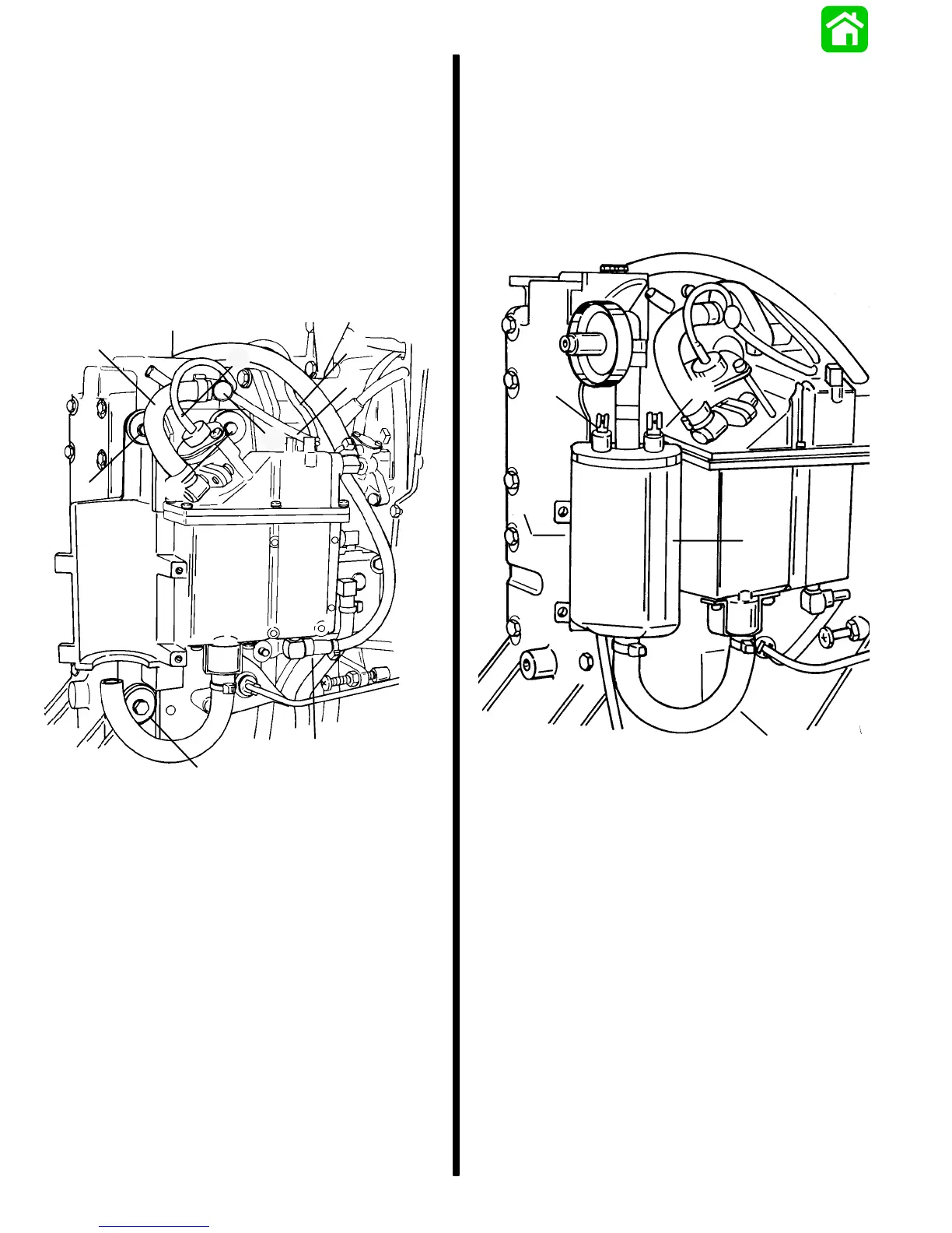
1. With vapor separator held in place install screws
securing vapor separator to engine block. Torque
screws to 45 lb. in. (5.0 N·m).
2. Connect oil inlet hose. Secure with hose clamp.
3. Connect bleed hose and vapor separator
vacuum hose.
4. Connect fuel pressure regulator vacuum hose.
5. Connect fuel rail re-circulation hose to manifold
fitting using hose clamp.
a
a
b
c
d
a
e
f
g
51786
a - Screws [Torque to 45 lb. in. (5.0 N·m)]
b - Oil Inlet Hose
c - Bleed Hose
d - Vapor Separator Vacuum Hose
e - Regulator Vacuum Hose
f - Recirculation Hose
g - Manifold Fitting
Electric Fuel Pump Installation
1. Install electric fuel pump with rubber blanket.
2. Connect fuel pump inlet hose. Secure with
sta-strap.
3. Connect POSITIVE lead and NEGATIVE lead.
4. Install mounting screws.
a
b
c
d
e
a - Electric Fuel Pump
b - Rubber Blanket
c - Inlet Hose
d - POSITIVE Lead (RED)
e - NEGATIVE Lead (RED/BLUE)

 Loading...