90-824052R3 JUNE 2002 ELECTRICAL - 2A-17
TRIGGER ASSEMBLY TEST
1. Remove 2 screws and lift outer switch box from
inner switch box. Refer to switch box(es) removal
and installation, following.
2. Disconnect all trigger leads from switch boxes.
3. Use an ohmmeter and perform the following
tests:
Test
Leads to
Resistance
Ohms
Scale
Reading
Between BROWN
Trigger Lead (with-
out YELLOW
Sleeve) and WHITE
Trigger Lead (with
YELLOW Sleeve)
1100-1400 R x 100
Between WHITE
Trigger Lead (with-
out YELLOW
Sleeve) and VIO-
LET Trigger Lead
(with YELLOW
Sleeve)
1100-1400 R x 100
Between VIOLET
Trigger Lead (with-
out YELLOW
Sleeve) and
BROWN Trigger
Lead (with YELLOW
Sleeve)
1100-1400 R x 100
4. If meter readings are not as specified, replace
trigger assembly. Refer to “Trigger Assembly
Removal and Replacement,” following.
CAUTION
Switch boxes must be grounded to engine before
cranking engine, or switch boxes will be
damaged.
IGNITION COIL TEST
IMPORTANT: Ohmmeter tests can only detect
certain faults in the ignition coils. Replace
ignition coil, if ohm- meter readings (listed in
chart, following) are not as specified. If coil tests
OK, and coil is still suspected of being faulty, use
Multi-Meter/DVA Tester (91-99750) or a voltmeter
and Direct Voltage Adaptor (91-89045) to
thoroughly check coil.
1. Disconnect wires from the positive (+) and nega-
tive (–) coil terminals.
2. Remove the spark plug (hi-tension) lead from coil
tower.
3. Use an ohmmeter and perform the following
tests:
NOTE: Copper wire is an excellent conductor, but it
will have a noticeable difference in resistance from
cold to hot temperatures. Reasonable variations
from these specified readings are acceptable.
Test
Leads to
Resistance
Ohms
Scale
Reading
Between (+) and (–)
Coil Terminals
.02-.04 R x 1
On BLUE Color
Coils Between Coil
Tower and Either (+)
or (–) Coil Terminal
(Mounted or Re-
moved)
800-1100 R x 100
4. If meter readings are not as specified, replace
ignition coil. Refer to ‘‘Ignition Coil Removal
and Installation,” following.
MERCURY (TILT) STOP SWITCH TEST
1. Remove mounting screw that secures mercury
switch and black ground wire to engine.
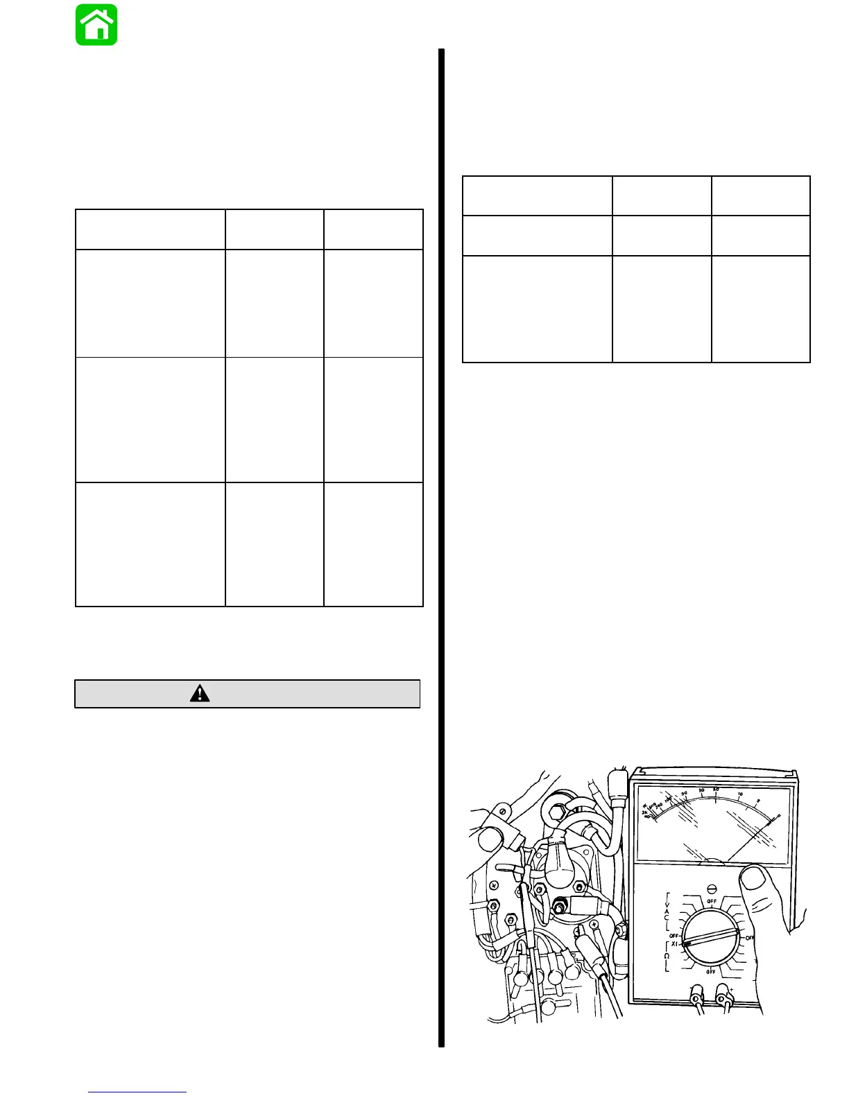
2. Connect an ohmmeter (R x 1 scale) between
black lead and black/yellow lead or terminal stud
on mercury switch.
3. Test mercury switch as follows:
a. Position mercury switch as it would be in-
stalled when engine is in “down” position. The
meter should indicate no continuity.
b. Tilt mercury switch up and tap end of switch
with finger. The meter should indicate
continuity.
c. If these readings are not obtained, replace
mercury switch.
51840

 Loading...