3C-16 - FUEL SYSTEMS 90-824052R3 JUNE 2002
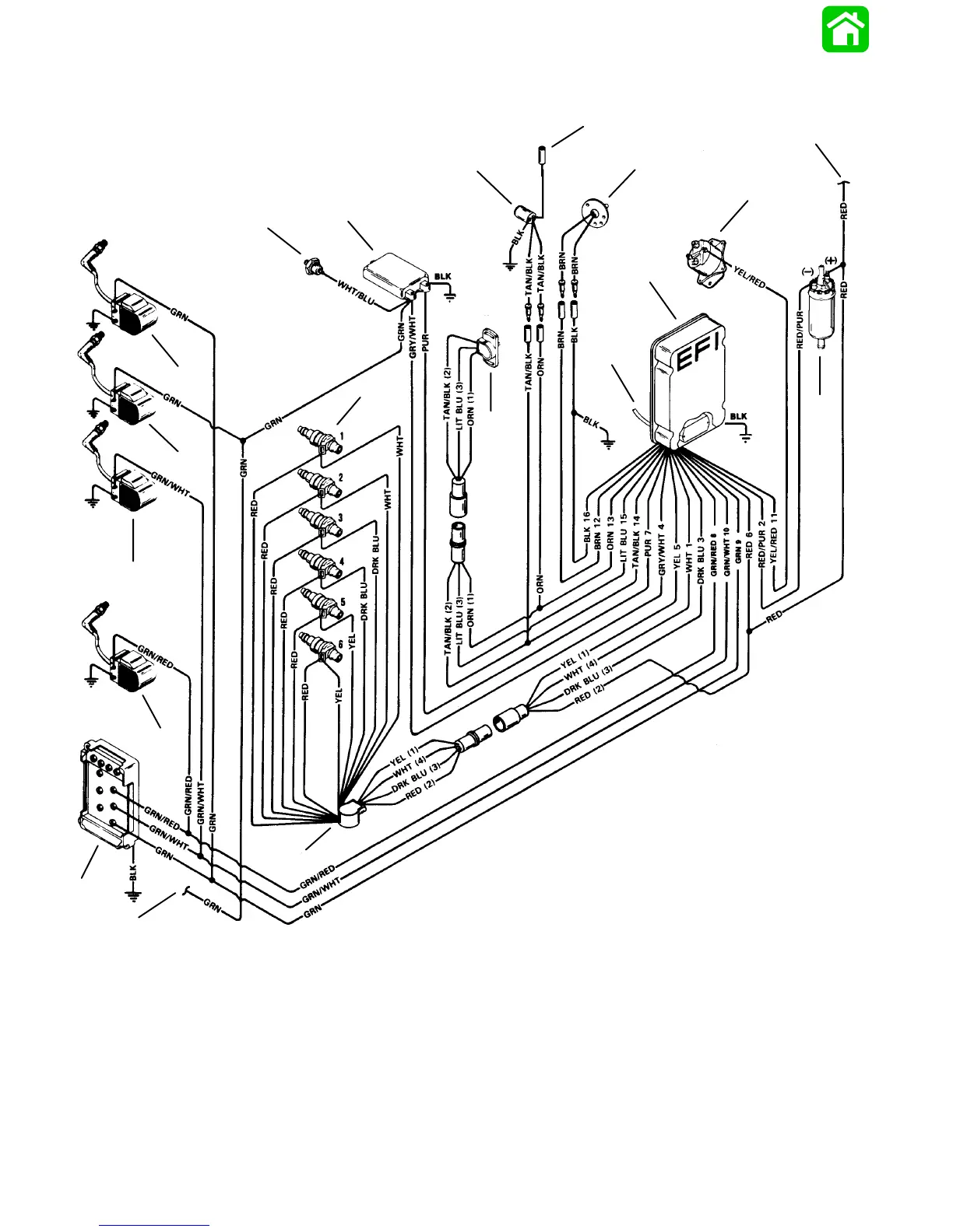
EFI Electrical Diagram
BLK = Black
BLU = Blue
BRN = Brown
GRY = Gray
GRN = Green
ORN = Orange
PNK = Pink
PUR = Purple
RED = Red
TAN = Tan
WHT = White
YEL = Yellow
LIT = Light
DRK = Dark
1
2
3
4
5
6
7
8
9
10
11
12
13
14
15
16
17
19
18
1 - Detonation Sensor*
2 - Detonation Module*
3 - Engine Head Temperature Sensor
4 - To Temperature Gauge
5 - Air Temperature Sensor
6 - Starter Solenoid
7 - 12 Volt Supply from Regulator
8 - Electric Fuel Pump
9 - Electronic Control Module
10- Manifold Absolute Pressure Sensor
11- Throttle Position Sensor
12- Fuel Injectors
13- Injector Wiring Harness
14- To Outer Switch Box
15- Inner Switch Box
16- #5 Ignition Coil
17- #3 Ignition Coil
18- #2 Ignition Coil
19- #1 Ignition Coil
*200 Models Only

 Loading...